Updating NESRGB4 MCU firmware
There are two versions of FPGA firmware. Boards with the date code on the silkscreen 2238 all have V2 FPGA firmware. Boards with the earlier date code 2231 almost all have V1 FPGA firmware except for a small amount which have "V2" written on the FPGA (the big 144 pin Lattice chip) itself.
FPGA firmware is not reprogrammable. MCU firmware is.
FPGA firmware V1
Version 1.0 MCU firmware contains two bugs.
- Controller button combinations (to change palette, in-game reset) are not recognised by the NESRGB on some NES controllers.
- The in-game reset feature does not work on front loading NES consoles.
NESRGB kits shipped between 22nd and 25th of August have version 1.0 firmware loaded.
Version 1.1 corrects both of these bugs.
FPGA firmware V2
Version 2.0 firmware contains a bug that causes it try to set the palette at power up before the FPGA is ready. This causes some boards to power up in the disabled state.
Version 2.1 corrects this by waiting an additonal 2ms for the FPGA to come up.
How to update
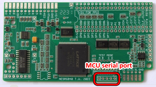
The microcontroller can be updated via its serial bootloader. Locate the serial port header. The pins are as follows (they are also labelled on the back of the board).
- +5V
- Ground
- TX
- RX
- PRG# (connect to ground)
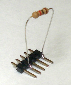
The PRG# pin is connected to ground to enable the bootloader. I recommend connecting it through a 1k resistor, this prevents damage to the board if the serial port header is accidentally connected backwards.
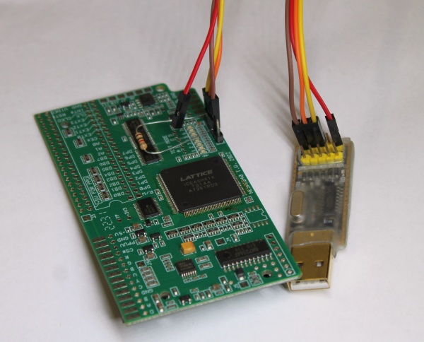
A USB to TTL to serial adapter and Windows PC is required.
A short 2.54mm pin strip makes it convenient to connect the serial port wires.
The RX and TX pins must be swapped around. That is, the RX pin on the USB to TTL serial adapter must be connected to the TX pin on the NESRGB board and vice versa.
Downloads
NESRGB MCU update tool V1.1
NESRGB MCU update tool V2.0
NESRGB MCU update tool V2.1

Procedure for updating the NESRGB board, powered from the USB to TTL serial adapter.
- Plug the USB to TTL serial adapter into the PC and install the driver if necessary.
- Run the NESRGB4 MCU update tool.
- Select the your USB to TTL serial adapter device from the COM port list. If you don't know which one it is, unplug it and see which one disappears from the list.
- Connect ground (GND), TX and RX wires to the NESRGB board (RX and TX must be swapped).
- Click the download button. The tool will report "Checking target MCU ... "
- Connect the +5V wire to NESRGB board to power it and the updating process will start automatically. Normally it takes about two seconds to complete.
Procedure for updating the NESRGB board, which is already installed in a console.
- Do steps 1-5 above with the console switched off. For step 6, simply switch the console on.
8/12/2022 - Added V2.0, V2.1 MCU firmware and bug description.
31/8/2022 - Page created.