Connect a Sega Game Gear to any TV
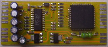
This a follow on from my Game
Gear RGB output design. I've condensed all the digital logic into
a single programmable logic chip. This allows room on the PCB for a
video encoder so those who live outside of Europe (who are bereft of RGB
SCART) can play the Game Gear on a TV too.
This new design is superior to the previous in all cases with the
exception of power consumption. Two voltage regulators supply +3.3V for
the CPLD (programmable logic) and +5V for the video encoder. The former
is regulated from the main +5V rail and the latter takes its power
directly from the battery. The reason for this is that I was worried
that I may overload the main +5v rail if I tried to pull an extra 100mA
(worst case) from it. This is quite an inefficient setup but the Game
Gear itself is hardly famous for battery life so I don't think anybody
will mind.
Video outputs available:
* Composite Video (NTSC)
* S-Video (NTSC)
* RGB Video
Version 1.0 (no longer available)
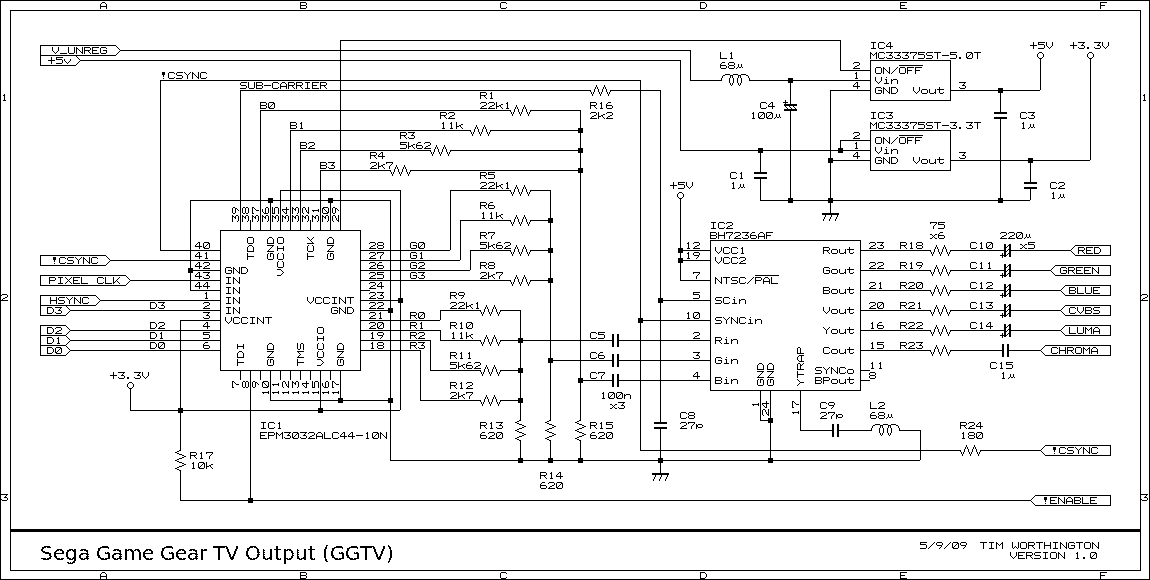
Circuit Diagram
Logic Equations - Written in AHDL and will
fit into a 32 macrocell CPLD.
Compiled CPLD binary - In Altera's POF format.
Compiled for EPM3032ALC44-10N.
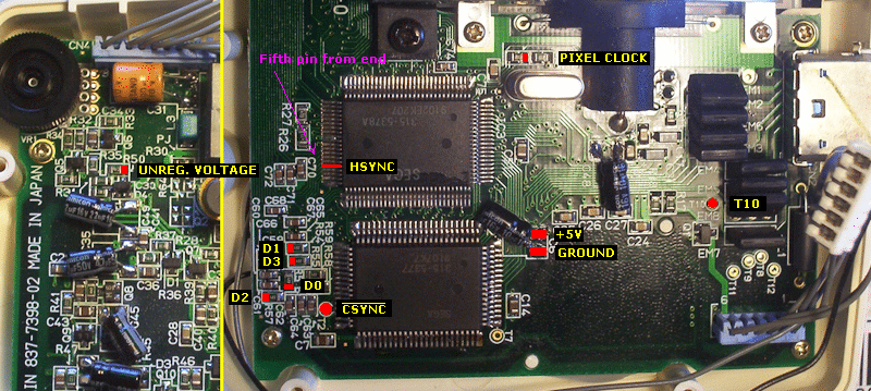
Installation diagram for 1 ASIC Game Gear (later
model)
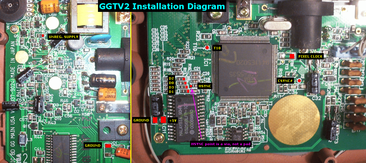
Installation diagram for 2 ASIC Game Gear
(earlier model)
Version 2.x
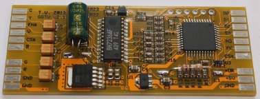
Circuit Diagram - Version 2.0
Circuit Diagram - Version 2.3
Logic Equations - Version 2.1 (13/6/2013) -
Written in AHDL and will fit into a 32 macrocell CPLD.
Compiled CPLD binary (V2.1) - In Altera's POF
format. Compiled for EPM3032ATC44-10N.
Installation diagram for 1 ASIC Game Gear
(later model)
Installation diagram for 2 ASIC Game Gear
(earlier model)
Note on 1 ASIC board installation: The solder point for the H. Sync
signal is a via -- an electroplated hole through the board. Carefully
scratch the green solder resist layer away before soldering a wire to
it. The GGTV board is not compatible with the late model Game Gear
consoles which contain the Sega 315-5682 ASIC.
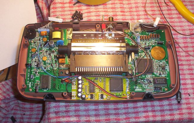
Installation
The board is designed to fit into the space below the cartridge slot.
It can be held in place with some hot glue at each end.
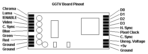
The pads to the left are outputs and those to the right are inputs,
with the exception of !ENABLE which must be connected to ground for the
board to operate. When the !ENABLE pin is not grounded (pulled to logic
high by a resistor on the board), the video encoder IC is switched off
and all outputs are disabled to conserve power. This signal can be used
to enable the video outputs only when an external cable is plugged in.
When playing Sega Master System games (with a cartridge adapter) the
Game Gear compresses the video signal to make it fit into the internal
LCD screen. This compressed video is not compatible with this output
board. The compression can be disabled by connecting point T10 to +5v
(logic high). In this state, the video will no longer display on the
internal LCD screen but a good, full screen picture will output from the
board. A switch or pin on the video connector can be used to select
whether SMS games render properly on the internal screen or video
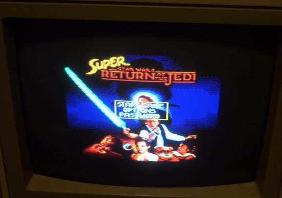
output. Game Gear games will have a large border (see
picture below) and this is unchanged by the state of T10.
It's important to keep the PIXEL CLOCK wire as far away from all the
other wires as possible. If it's too close you will get glitchy video on
some games. Multiple ground points are provided. You must solder at
least two of them (ideally, one on each side of the board) to ensure
there is a good ground connection.
There is more information available on my other page, How
to Connect a Sega Game Gear to a TV via RGB SCART. When comparing
diagrams, HSYNC (on this page) = HLATCH (on the other page).
Where to buy?
Buy one in the online shop.
For questions and comments please email.

Last modified 22/6/2017