AV-Driver for Arcade RGB 'Supergun'
A device for connecting an JAMMA arcade game board to an TV is generally known as a Supergun. It contains a power supply, arcade controls (or other controller interface), and some electronics to adapt the audio/video signals to television standards. The video signal (usually) has the same timing as NTSC video, but the electrical properties are different to a standard TV/video monitor. It's an analog signal with TTL level amplitude (3-5 Vpp). This makes the video circuit simpler for both the game board and monitor. The Game board has an audio amplifier built in which can drive a speaker directly. The Supergun will either have a audio attenuator or just a speaker inside.An RGB Supergun would typically have a audio/video attenuation circuit like this inside.
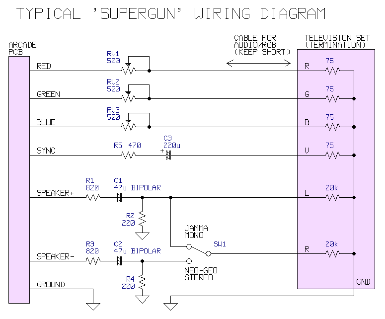
This circuit has three separate potentiometers connected, one for each colour signal. This forms a voltage divider with the termination resistor inside the TV set. It usually works acceptably but there are some problems.
- The adjustment is complicated. The three pots must be adjusted to the same value or the colour balance will be poor.
- It may load the arcade board's video circuit. Using this video attenuation circuit, the load on the arcade board video circuits is lower (75-575 ohms depending on the pot position) than any arcade monitor (1-5k ohms). This makes it difficult, or in some cases impossible, to connect the arcade board to both an arcade monitor and a 75 ohm monitor (TV, capture device, etc) at the same time.
- The impedance mismatch means the video cable must be kept short to avoid distortion.
The audio part is a fairly ordinary speaker to line level attenuator. There is a stereo/mono switch for Neo Geo boards. For normal monaural JAMMA boards the speaker- pin is not connected (this isn't ground). The performance of an audio attenuator circuit like this is usually fine.
Here's another circuit for an RGB Supergun. This time using the AV-Driver and a 10k linear multi-gang potentiometer.
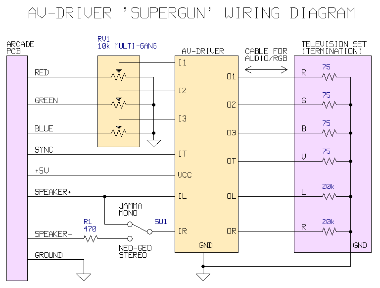
Now there is just one control for all three colours together, making it easier to adjust. The purpose of R1 is only to protect the audio amplifier on the game PCB in case somebody changes the position of SW1 with the power on.
The load on the arcade game's video signal is very light, so it may be installed into an existing arcade machine to provide a standard 75 ohm RGB video output without having any impact on the internal monitor. The cable between the AV Driver and the TV set may be long if it's built from 75 ohm coax.
Multi-gang Potentiometer Calibration
It is an unfortunate fact that multi-gang potentiometers are usually not matched between each gang. If the gangs are chosen arbitrarily, it could lead to a gain error of up to 20% between colour channels which is unacceptable. The solution is to use a six gang potentiometer, test all six gangs, and pick the three which match the closest. This way it's possible to get a less than 5% error over the entire range.
Here's the test procedure. It requires a 5V power supply (doesn't have to be accurate, just stable) and a multimeter.
- Solder all gangs' terminal 1 pins together.
- Solder all gangs' terminal 3 pins together.
- Set the multimeter to DC volts mode.
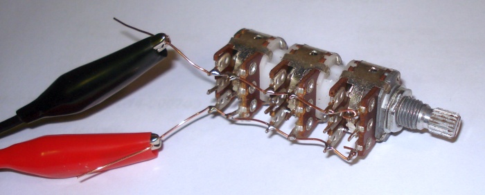
- Connect the the ground lead of the power supply to terminal 1 and the +5V power lead to terminal three. See the photograph below. If you connect the multimeter between ground and the middle pin the voltage measures should vary between 0 (fully anticlockwise) and 5V (fully clockwise).
- Print or draw the table below on a sheet of paper.
- Measure the exact value of the of the power supply voltage and write it down.
- Measure the voltage between middle pin of gang A and ground. Adjust the knob until it measures approximately 1V. Write down the exact value in the table in the first column. Make the same measurement for each gang and write them all down in the first column.
- Adjust the knob again so it's approximately 2V at the middle pin this time. Record all the values again for all six gangs.
- Repeat two more times at 3V and 4V until the table is full.
- Measure the power supply voltage again to make sure it hasn't drifted while performing the test.
| Start of test | |
| Power supply voltage |
| 1V | 2V | 3V | 4V | |
| Gang A (knob end) | ||||
| Gang B | ||||
| Gang C | ||||
| Gang D | ||||
| Gang E | ||||
| Gang F |
- Pick the three gangs with closest matched values. Try to get below 5% error.
- As an example, the table below is filled with data measurements from pot in the photo above. The three closest gangs are highlighted in pink. The worst case error measured is 3% (1V range).
- Mark the three matching gangs with a permanent marker.
| 1V | 2V | 3V | 4V | |
| Gang A (knob end) |
1.05 |
2.01 |
2.95 |
3.83 |
| Gang B | 1.09 |
2.05 |
3.01 |
3.85 |
| Gang C | 1.02 |
2.06 |
3.13 |
4.04 |
| Gang D | 0.94 |
1.95 |
3.02 |
3.97 |
| Gang E | 1.03 |
2.08 |
3.11 |
4.03 |
| Gang F | 1.00 |
2.03 |
3.05 |
4.00 |
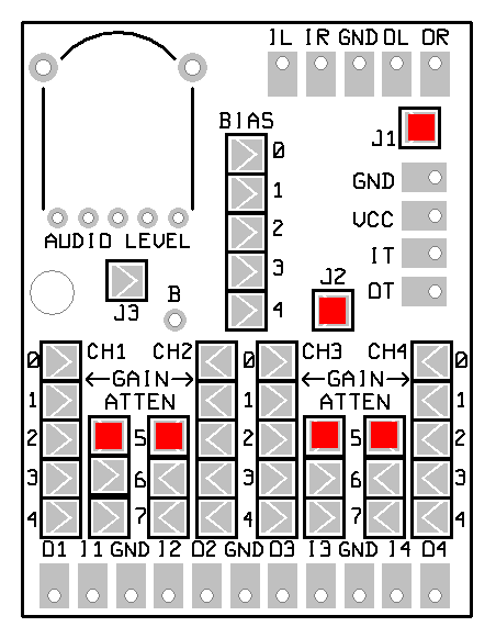
AV-Driver Jumper Setting
|
 |

Change Log
9/6/2016 - Page created.