|
The CLOCKFIX10 board can be installed onto a NESRGB40 board (22.31 date code) to fix the Interrupt detection firmware bug. This is a way of fixing a firmware bug with external hardware.
The board looks like this.
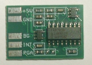
+5V and GND are for power.
BG is an input that connects to the output of the comparator.
INT is a input which connects to the Interrupt signal from PPU pin 19.
PGA is an output which connects to the FPGA.
Installation procedure
1. Remove the PPU from the NESRGB board. If it is soldered on it will need to be desoldered. Once desoldered, make sure all pins wiggle freely before attempting to remove the PPU. Otherwise the plated through holes of the NESRGB board may be damaged.
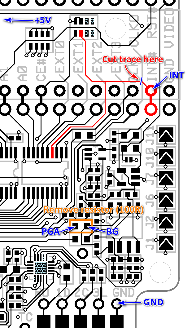
2. Cut the trace from the INT# pin 19 of the PPU, close to the pad, as shown on the diagram above.
3. Remove the 100 ohm SMT resistor marked in orange in the above diagram. There are much smaller resistors around it, be careful not to disturb them.
4. Solder five wires between the INTFIX10 board and the NESRGB pads as indicated on the diagram. The +5V pad of the INTFIX10 should be connected to the +5V pad of the NESRGB board.
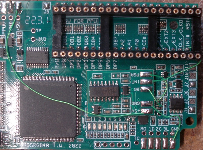
This is what the board looks like once it is installed.
Last updated 15/2/2023
|