RGB SCART to JAMMA Adapter VERSION 2.0
Instructions
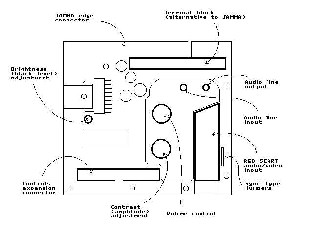
Audio/Video Input
I highly recommend the use of official or high quality third party cables. Poor quality
cables are often wired incorrectly, break easily, and cause a buzzing sound to be heard
through the audio. If you wish to build your own video cables, might I suggest my page of Game Console RGB
SCART Cable Diagrams as a reference? Take note that this adapter does ignores the
SCART switching voltages on pins 8 and 16.
All pre made SCART cables will used composite video for sync information. If for some reason you would like to connect a device which does not have composite video available (such as an Amiga or other microcomputer) you may want to construct a non-standard cable with a TTL composite sync signal in place of the composite video. There are a set of jumpers located next to the SCART socket labeled TTL and 75.
75 on, TTL off = Terminated composite video. Default.
75 off, TTL off = Unterminated composite video. Try this if you have any sync related
problems.
75 off, TTL on = TTL composite sync or TTL horizontal sync.
The video amplifier will not function without some form of sync input.
Power
The adapter requires a well regulated 12 volt supply capable of supplying at
least 1 amp of current. This can be connected via the JAMMA card edge or the terminal
block. Other voltage from the JAMMA power supply are not used.
Sometimes switching power supplies have trouble keeping
regulation without a load on the +5V line. For these situations you will need to connect a
power resistor (supplied) between the +5V line and ground to act as a dummy load. This
resistor will get hot so should ideally be connected directly to the power supply, away
from stray fingers. 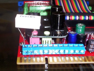
Refer to the photo to the right on connect the white power resistor --->
Speaker Output
The speaker must have an impedance of 8 ohms or higher (two 4 ohm speakers in
series, or two 16 ohm speakers in parallel are ok) speakers of lower impedance or two 8
ohm speakers in parallel may overload the amplifier. The speaker would normally be wired
to the JAMMA but may be connected to the terminal block if desired.
The onboard amplifier is monaural (i.e. has only one channel) which mixes both left and right audio signals together. The speaker must be connected between speaker -ve and speaker +ve, not between either speaker terminal and ground as is normally done with a HiFi amplifier.
The volume control adjusts volume of the sound, as all good volume controls do.
Video Output
Red, Green, and Blue video is output from the JAMMA card edge as well as a
composite sync signal. Video and composite sync are also available from the terminal block
along with separate horizontal and vertical sync outputs (I hear some pre-JAMMA arcade
monitors require sync signals like this).
There are two controls which affect the video signal, contrast and brightness. The contrast control adjusts the amplitude of the video signal, the brightness adjusts the black level. The brightness control is a high accuracy 4 turn trimpot which is pre adjusted to a black level of 0.2V. This is suitable for most monitors and will usually require no additional adjustment. Note that if the black level is set to less than 0.05V the picture may cut out, even with the contrast at maximum. There are is a square test point next to the brightness trimpot. I use this to calibrate the black level but you may use them too, should you wish to do so.
Take note that the contrast can be adjusted higher that the previous model. Be careful not to over drive your monitor.
Audio Output
The red 3.5mm jack above the SCART socket is a buffered line level stereo audio
output from the game console. Useful if you feel the built in audio amplifier is far too
puny and would like to use something with a bit more heft.
The level is unchanged by the volume control.
Audio Input
The green 3.5mm jack above the SCART socket is a buffered line level audio input.
This is a switched jack, so the audio in from the SCART input (if any) will be switched
off.
Terminal Blocks (blue) - From right to left.
| GND | Ground |
| 5V | +5V Input (not required) |
| 12V | +12V Input |
| HS | Horizontal Sync Output (active low) |
| VS | Vertical Sync Output (active low) |
| SPKR | Speaker Output Positive |
| SPKR | Speaker Output Negative |
| RED | Red Video Output |
| GREEN | Green Video Output |
| BLUE | Blue Video Output |
| CSYNC | Composite Sync Output (active low) |
| GND | Ground |
Control Expansion Connector
| 1 | Second Player Fire Button 5 | 2 | First Player Fire Button 5 |
| 3 | Second Player Fire Button 4 | 4 | First Player Fire Button 4 |
| 5 | Second Player Fire Button 3 | 6 | First Player Fire Button 3 |
| 7 | Second Player Fire Button 2 | 8 | First Player Fire Button 2 |
| 9 | Second Player Fire Button 1 | 10 | First Player Fire Button 1 |
| 11 | Second Player Right Joystick | 12 | First Player Right Joystick |
| 13 | Second Player Left Joystick | 14 | First Player Left Joystick |
| 15 | Second Player Down Joystick | 16 | First Player Down Joystick |
| 17 | Second Player Up Joystick | 18 | First Player Up Joystick |
| 19 | Second Player Start Button | 20 | Coin Switch 1 |
| 21 | Coin Switch 2 | 22 | (reserved) |
| 23 | Slam Switch | 24 | Test Switch |
| 25 | First Player Start Button | 26 | OSD Blue Input |
| 27 | OSD Green Input | 28 | OSD Red Input |
| 29 | OSD Enable Input | 30 | OSD Sync Input |
| 31 | Vertical Sync Output | 32 | (reserved) |
| 33 | +12V | 34 | +12V |
| 35 | +5V | 36 | +5V |
| 37 | +5V | 38 | Ground |
| 39 | Ground | 40 | Ground |
CTRLEXP1: Terminal Blocks (green)
| 2PCN | Coin Switch 2 | 1PCN | Coin Switch 1 |
| 2PST | Second Player Start Button | 1PST | First Player Start Button |
| 2PUP | Second Player Up Joystick | 1PUP | First Player Up Joystick |
| 2PDN | Second Player Down Joystick | 1PDN | First Player Down Joystick |
| 2PLT | Second Player Left Joystick | 1PLT | First Player Left Joystick |
| 2PRT | Second Player Right Joystick | 1PRT | First Player Right Joystick |
| 2PF1 | Second Player Fire Button 1 | 1PF1 | First Player Fire Button 1 |
| 2PF2 | Second Player Fire Button 2 | 1PF2 | First Player Fire Button 2 |
| 2PF3 | Second Player Fire Button 3 | 1PF3 | First Player Fire Button 3 |
| 2PF4 | Second Player Fire Button 4 | 1PF4 | First Player Fire Button 4 |
| 2PF5 | Second Player Fire Button 5 | 1PF5 | First Player Fire Button 5 |
| GND | Ground | (reserved)* | |
| GND | Ground | Slam Switch* | |
| TEST | Test Switch |
* No screw terminals exist for these signals, though they can bee added by request.
CTRLEXP2: JAMMA Pass-Through
| Parts Side (top) | Solder Side (bottom) | ||||
| Description | Pin | Passed through? | Description | Pin | Passed through? |
| Ground | 1 | YES | Ground | A | YES |
| Ground | 2 | YES | Ground | B | YES |
| +5V (not required) | 3 | YES | +5V (not required) | C | YES |
| +5V (not required) | 4 | YES | +5V (not required) | D | YES |
| -5V (not required) | 5 | YES | -5V (not required) | E | YES |
| +12V | 6 | YES | +12V | F | YES |
| KEY | 7 | KEY | H | ||
| N/C | 8 | N/C | J | ||
| N/C | 9 | N/C | K | ||
| Speaker +ve | 10 | Speaker -ve | L | ||
| N/C | 11 | N/C | M | ||
| Red video | 12 | Green video | N | ||
| Blue video | 13 | Composite Sync | P | ||
| Ground | 14 | YES | Service Switch | R | |
| Test Switch | 15 | YES | Slam Switch | S | YES |
| Coin Switch 1 | 16 | YES | Coin Switch 2 | T | YES |
| First Player Start Button | 17 | YES | Second Player Start Button | U | YES |
| First Player Up Joystick | 18 | YES | Second Player Up Joystick | V | YES |
| First Player Down Joystick | 19 | YES | Second Player Down Joystick | W | YES |
| First Player Left Joystick | 20 | YES | Second Player Left Joystick | X | YES |
| First Player Right Joystick | 21 | YES | Second Player Right Joystick | Y | YES |
| First Player Fire Button 1 | 22 | YES | Second Player Fire Button 1 | Z | YES |
| First Player Fire Button 2 | 23 | YES | Second Player Fire Button 2 | a | YES |
| First Player Fire Button 3 | 24 | YES | Second Player Fire Button 3 | b | YES |
| First Player Fire Button 4 | 25 | YES | Second Player Fire Button 4 | c | YES |
| First Player Fire Button 5 | 26 | YES | Second Player Fire Button 5 | d | YES |
| Ground | 27 | YES | Ground | e | YES |
| Ground | 28 | YES | Ground | f | YES |
Appendix II: Electrical Specification
Input Voltage Ratings
| Description | Min | Typ | Max | Unit |
| Power supply voltage | 11 | 12 | 13 | Vdc |
| Red, Green, Blue video | 0.7 | 2 | Vp-p | |
| Composite video (JP3 off) | 0.7 | 1 | 2 | Vp-p |
| Composite sync (JP3 on) | 1 | 5 | Vp-p | |
| Max sustained DC voltage into R,G,B,CV input | 2.5 | Vdc | ||
| Left, Right audio | 0.2 | 0.5 | 2 | Vp-p |
Input Impedance Characteristics
| Description | Typ | Unit |
| Red, Green, Blue video | 75 | Ohms |
| Composite video (JP2 on, JP3 off) | 75 | Ohms |
| Composite video (JP2 off, JP3 off) | >1k | Ohms |
| Composite sync (JP2 off, JP3 on) | 800 | Ohms |
| Left, Right audio | 10k | Ohms |
Output Voltage Characteristics
Power supply = 12V / R, G, B video input = 0.7Vp-p / CV input = 1Vp-p / L, R
audio input 0.5Vp-p
Horizontal, Vertical, Composite sync output load = 1.5k / R, G, B video output load = 1k
| Description | Min | Typ | Max | Unit |
| Red, Green, Blue video (AC) (contrast) | 0 | 7 | Vp-p | |
| Red, Green, Blue video offset (brightness) | 0.1 | 3 | Vdc | |
| Horiz, Vert, Composite Sync logic high | 2.5 | 3 | V | |
| Horiz, Vert, Composite Sync logic low | 0.24 | 0.5 | V |
Other Characteristics
| Description | Min | Typ | Max | Unit |
| Bandwidth (-3dB) @ max contrast | 50 | Mhz | ||
| Peak voltage on R,G, B video output (before distortion) | 7 | 7.5 | V | |
| Minimum video output black level (before cut out) | 0.05 | V | ||
| R, G, B video output impedance | 300 | ohms | ||
| L, R Audio output impedance | 300 | ohms | ||
| Speaker load impedance | 6.5 | 8 | ohms | |
| Power draw (audio amp disabled) | mA | |||
| Power draw (audio amp active) | 1000 | mA | ||
| Gain mismatch between R, G, B video | 3.5 | % | ||
| R, G, B video voltage gain | 0 | 7.5 |
Appendix IV: Ordering Information
See ordering page.
Page created 3/1/2011.
Updated 22/8/2012.