Control Expansion Board for Playstation 1/2 This board converts parallel inputs from arcade controls to the Playstation 1/2 protocol. It has been designed specially for use with the SCART To JAMMA Adapter V2, but may also be used in a stand alone configuration. The board is programmable, and can support many differently programmed profiles which may be selected at any time. Basics A look at the hardware. |
Input connector (CN1) - The SCART to JAMMA Adapter connects here through a flexible ribbon cable. Doing so connects all the switches from all the joysticks and buttons connected to the JAMMA harness through to inputs on the Playstation controller board. Kick harness board - This provides extra inputs for "kick harness" connectors which are not part of the original JAMMA stardard. See the kick harness section for more details. Player 1 and Player 2 controller plugs - Plug them into the Playstation 1/2 console or converter(s). It is recommended that both Player 1 and Player 2 are plugged in even when you only plan to use Player 1 functions. Dip switches (SW3) - This pair of small switches is used to set the rapid fire speed. P1 & P2 analog indicators - These indicators work in exactly the same manner at the analog indicators on a Dual Shock controller. They are also used as status indicators during programming and test modes. Key switch - The single button user interface. The key switch indicator will come on every time the key switch is pressed. Display - The seven segment LED display. The decimal point serves the purpose of a power indicator. Misc. switch - This is connected to one of the control inputs (#26), and may be programmed to any Playstation controller function. Abstract terms defined. These terms are used throughout the manual. Board - This refers to the Control Expansion Board for Playstation 1/2 itself Input - An input is a hardware connection between a switch (arcade pushbutton or joystick) and a connection on the board. Inputs may be programmed to map to functions. Function - A software command between the board and the Playstation console. Assert - When an input is to be asserted, it refers to the action of closing the connection between the input pin and ground. If there is a switch connected to the input, such as an arcade pushbutton or joystick, asserting is only a matter of pressing the button or moving the joystick in the appropriate direction. Profile - A 'mapping file' - Refering to a data set which holds the information about which input correstponds to which function. The profiles are stored in the internal memory (EEPROM). General operation. Plug in the Player 1 and Player 2 controller plugs, the Input connector (CN1), and the kick harness (if required). It is recommended that everything be plugged in before switching the Playstation or Playstation 2 console on. The board is capable of holding up to 16 user programmable profiles in its internal memory. Press the the key switch at any time to cycle through the available profiles. If you are using the board for the first time, the internal memory will be empty. You must create at least one new profile before the board will do anything useful. See the programming section for more information. Every time you create a new profile, it will be represented on the display by another hexidecimal digit in the series. (eg. 0, 1, 2, 3, 4, 5, 6, 7, 8, 9, A, B, C, D, E, F). The blue dip switches (CN3) adjust the rate of fire for those inputs which have been programmed with the rapid fire function.
Programming Creating a new profile. 1) Press the key switch until the new profile marker ( 2) Press and hold the key switch for six seconds to enter programming mode. 3) Once you have released the key switch, the key switch indicator will remain on to show that the device is in programming mode. Now the display will alternate between the two states shown below:
Press the key switch again at the appropriate time to make a selection. They are functionally identical, the choice is provided for compatibility reasons only. 4) It is now time to assign the functions of a Playstation controller to the joystick and buttons on your arcade control panel. The functions will be presented one at a time on the display and you can either assign it to a particular button/joystick input by asserting that input or you can skip over that function by pressing the key switch. It is possible to assign a function to multiple inputs by asserting the relevant inputs together. For example to assign 'button 1' and 'button 2' on the control panel to the same function you would depress 'button 1' then depress 'button 2' then release 'button 2' then release 'button 1'. It is not possible to assign more than one function to the same input. The P1 indicator will come on to show you are assigning Player 1 controller functions.
5) You have gone through all the functions listed above and either assigned them or skipped over them. The P1 indicator light will go out and the P2 indicator will come on. Repeat the procedure for the Player 2 functions. After the P2 functions are all assigned or skipped, both the P1 and P2 indicators will come on. At this point there are two more functions that need to be set before the profile can be saved. They are special features which are not found on standard Playstation controllers. 6) If you wish to be able to change current profile with an external switch or button (other than the key switch), assert it now. This is useful if the controller board is to be mounted in a place where it is difficult to access the key switch in order to change profiles. If this function is used it should be assigned to the same input on every profile. If you do not want to use this function, press the key switch to skip over it.
7) Now it is time to set up rapid fire. At this time assert the button/joystick inputs which you would like to fire rapidly. When you are done, press the key switch to save the profile. If you do not want any rapid fire inputs, just press the key switch to skip over this function and save the profile.
Now the profile has been saved to internal memory and currently selected with its number reported on the display. Make sure you make a note of this number for future reference. The key switch indicator will go out to indicate the device is in normal mode. Overwriting an existing profile. The procedure is the same as above, but hold the key switch while an active profile is selected. Deleting an existing profile. To delete a profile: Overwrite the existing profile, but during the programming procedure skip over every function with the key switch. The empty profile will then be deleted. Note that when a profile is deleted, the selection wraps around at that point. For example, if you have five profiles (0,1,2,3,4) programmed and you delete number 4, you would be able to access the remaining four profiles (0,1,2,3) normally. However, if you had five profiles (0,1,2,3,4) programmed and you deleted number 2, you would only be able to access profiles 0 and 1, leaving profiles 3 and 4 inaccessable. For this reason I recommend deleting only the last profile in the list. Test & Troubleshooting: Memory Test This will test internal EEPROM storage which is used to store profiles an other data. Note that running the memory test will completely erase the memory (just like a new one). To perform a memory test. 1) Plug the board into a Playstation game console that is switched off. 2) Set the blue dip switches to the following positions.
3) Press and hold down the key switch. 4) Switch on the Playstation console that the board is connected to, keeping the key switch depressed. 5) Keep holding the key switch for a further 60 seconds or so. The display will be blank during this time. 6) Once you see the display and P1 & P2 indicators come on, you will know have entered memory test mode. Release the key switch to start the test. 7) The test will take a short moment to run. Then the display will show the result of the test and start to blink.
8) Once you have observed the result you may switch off the Playstation console. This will reset the board to normal operation the next time it is powered up. Test & Troubleshooting: Input / Output Test This is the most useful of the test modes. It can be used for checking that the control inputs, switches, indicators, and display are all operating correctly. It is also useful for checking your JAMMA/control panel wiring. Enter I/O test mode. 1) Plug the board into a Playstation game console that is switched off. 2) Set the blue dip switches to the following positions.
3) Press and hold down the key switch. 4) Switch on the Playstation console that the board is connected to, keeping the key switch depressed. 5) Keep holding the key switch for a further 60 seconds or so. You can use the time to double check that the dip switches are in the correct position. You do not want to enter the memory test by accident! 6) Once you see the display and P1 & P2 analog indicators come on, you can release the key switch. 7) The key switch indicator is blinking. You are now in I/O test mode. The features of I/O test mode. 1) The P1 & P2 indicators will show how many inputs are asserted currently.
2) The display will report the number of an asserted input. If more than one input is asserted at once, the display will only report the lower of the two numbers. For example:
3) The key switch indicator is blinking constantly. The position of the dip switches will vary the rate. This tests the dip switches.
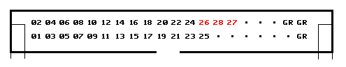
4) If the key switch is pressed, all segments of the display will light up and both P1 & P2 indicators will come on. This tests the display and P1 & P2 indicators. To test the operation of control inputs. 1) Enter I/O test mode (see above) if you have not already. You must have the control inputs (CN1) and any kick harnesses disconnected at this time. 2) The display should be blank and the P1 & P2 indicators should be off. 3) Find the test wire which was supplied with the board in a separate bag. 4) Connect one end of the test wire to a ground pin (labeled GR) on connector CN1. Use the other end of the wire to probe the other pins on the connector. Check that the P1 indicator comes on for each input asserted. If P2 comes on then you have asserted two inputs at once or there is a short circuit between two inputs. Check the inputs on the kick harness using the same method. CN1
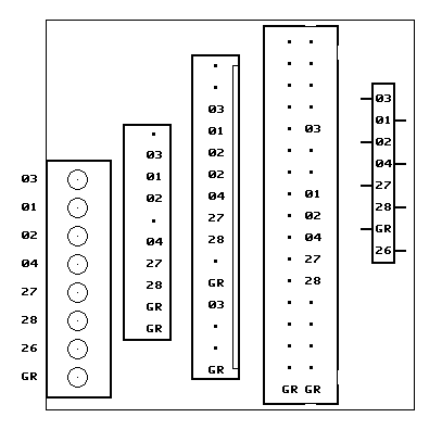
Note: Inputs 26, 27, 28 are not connected to CN1 by default, see the Technical section for more detail. CN2 / Kick Board
To test the operation of switches, indicators, and the display. 1) Enter I/O test mode (see above) if you have not already. It is best to have the control inputs (CN1) and any kick harnesses disconnected at this time. 2) You will observe that the key switch indicator is blinking. If you change the position of the dip switches, the blink rate of the key switch indicator will change. Try all four combinations, observing the increasing speed of the blinky light. 3) Currently the display is blank except for the decimal point. The decimal point is always on, it is effectively a power indicator. The P1 and P2 analog indicators are off. 4) Press and hold the key switch. Now all segments of the display will come on and so will the P1 and P2 analog indicators. 5) Release the key switch. The display and P1 & P2 indicators are off again, as they were in step 3. Once you are finished with I/O test mode, you may switch off the Playstation console. This will reset the board to normal operation the next time it is powered up. Technical Using the board in isolation. The Playstation 1/2 Controller board is designed primarily as an expansion to the SCART to JAMMA Adapter V2. Though it will also work as a general purpose Playstation controller encoder. For example in a NON-JAMMA arcade environment where audio/video amplification is not necessary, or perhaps in a detachable arcade control panel. Extra inputs on CN1. Inputs 26, 27, and 28 are not connected to the controls input connector (CN1) and are designed to be used with a kick harness. If you are not using a kick harness and would like the be able to access these inputs from CN1 then connect the solder jumpers JP4, JP6, and JP5 (respectively). EEPROM write protection. If the JP9 solder jumper is connected, the EEPROM (internal memory) is write protected and no changes to profiles can be made. It is strongly recommended that the board be set to profile '0' before it is unplugged and the solder jumper is connected. If any other profile is set, the table below will not be accurate. Write protection is useful when the board is located somewhere with poor access. If this is the case, it is best to program the profiles, making sure there is a button on the control panel that is assigned to the 'next profile' function in every profile, and then set the write protection solder jumper. Now you can jump to the profile desired by pressing the 'next profile' button the appropriate number of times. If you make a mistake, just wait three seconds for the selection timeout to occur and make your selection again.
Note: Do not change the state of any solder jumpers other than JP4, JP5, JP6, and JP9. The others are for testing/software programming and are not meant to be changed by the user. Please leave them alone. Specifications. Electrical Supply voltage min: 3.0V Supply voltage max: 5.5V Supply current max: 55mA Input pull up: 10 k to VCC on each input. Operational Unique inputs: 28 Players supported: 2 EEPROM memory capacity: 512 bytes Additional processing delay (lag): < 1 ms Mechanical Width: 114.6 mm Depth: 83.7 mm Height without kick board: approx. 18 mm Height with kick boad: approx. 30 mm Player 1 and 2 cable length: approx. 2 m Width of kick board alone: 43.2 mm Depth of kick board alone: 45.7 mm 19/8/2012 Tim Worthington Instruction Manual Revision 0 |