A Note On Sync
There are two methods of transmitting sync information in use for 15 kHz RGB video. By far the most common is the use of composite video for sync which is used by SCART, Japanese RGB-21, pro monitors, and other television RGB systems. The other sync transmission method is TTL sync. This is mostly used in RGB monitors which were dedicated to a particular task. Arcade monitors, 1980s computer monitors (such as the Commodore 1084 series), and some specialised pro monitors fall into this category. Also there are some VGA systems which accept 15 kHz RGB video and these use the VGA sync method (separated TTL). Monitors which only accept TTL sync lack a particular circuit, known as a sync stripper, which is used for extracting the sync information from a composite video signal. It is possible to plug in an external sync stripper to make these monitors compatible with composite video sync.
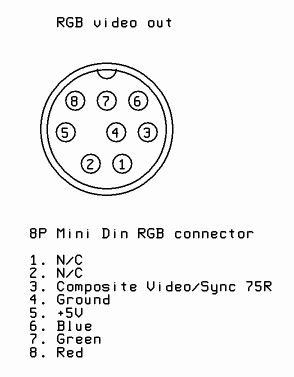
When wiring the video connector you may choose either composite video (V), luma (Y), or TTL composite sync (CS#). All three will work equally well when displaying RGB video on a system expecting composite video sync. When connecting to a SCART system I recommend using composite video(V), as this gives you the option of viewing this if RGB is not available. The TTL composite sync (CS#) signal is compatible with systems expecting both composite video sync and TTL sync. I recommend this if you want the best compatibility with obscure video monitors. Note that this is only true of my products. Normally, TTL sync (from an arcade PCB for example) is not guaranteed to work correctly when connected to a video input.
Other notes
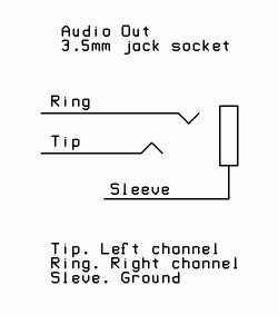
Audio is on a separate connector to prevent video noise getting into the signal. This completely solves the 'buzzing sound on RGB SCART' problem that many people with cheap SCART cables have experienced.
Reasons for the decision.
I preferred to use an RGB connection standard that was already used by somebody else. The connection must use a connector which is widely available, easy to mount, and is not dedicated to a particular purpose (such as a USB connector is, for example). It is also unacceptable to require additional components connected to the video signal. This was often done by Sega and other game console manufacturers to reduce the cost of their game consoles at the expense of the cables.
I stated by looking through the list of Game Console RGB SCART Cable Diagrams. So many use proprietary connectors or require extra components! The only one to meet the criteria is the Neo Geo AES, a console known for its variable RGB video quality. Some people have used Sub-D connector in these circumstances... I considered this but the D shaped connector is quite difficult to mount. VGA connector is not suitable because the signals are not compatible with VGA and this will cause confusion. SCART connectors are too large and funny shaped...
I settled on the connection from the Micomsoft XRGB-mini Framemeister. This uses a small 8 pin mini din connector for audio and RGB video. Sync on composite video (75 ohm terminated). It's basically SCART/Jap RGB-21 with all the extraneous pins removed. The only change I make is to leave off the audio pins. The signals audio and video signals should go through separate cables so that they don't interfere with one another. This is the simple solution to audio interference problem. The alternative would be to use special cables that keeps the signals separate along its length. This would make pre-made cables significantly more difficult to make (and hence more expensive) with little added benefit. People are used to plugging in multiple connectors at once anyway.
The choice of a 3.5mm jack socket instead of a pair of phono (RCA) connectors was mostly an aesthetic one. The mini din connectors that I supply are small and do not protrude much. The 3.5mm jack protrudes the same amount and takes up very little panel space. This is important for space constrained consoles such as the Famicom.