Software and Errata for NESRGB Kit
Firmware
The new version 2 hardware, released in February 2019, is not compatible with the old firmware (and vice versa).
For version 1.X hardware
Version 1.7 - I spent more time on RAM access logic and it should be solid now. Used from early 2014 to June 2016.
Palettes are
- RGB Playchoice (Nestopia 2013)
- FCEUX (Nestopia 2013)
- YUV (Nestopia 2013)
Version 1.8 - Same as version 1.7, but with a palette change. Used from June 2016 to February 2019.
Palettes are
- RGB Playchoice (Nestopia 2013)
- FCEUX (Nestopia 2013)
- Unsaturated-V6 (Firebrandx June 2016)
Version 1.9 - This is a special version with the de-jitter feature built in. Make sure you read the further information about it so you know what you're getting. This in not a stock firmware.
Palette is
- Unsaturated-V6 (Firebrandx June 2016) only
Version 1.9A - Same as 1.9 but with a different palette. Make sure you read the further information about it so you know what you're getting. This in not a stock firmware. (file fixed on 26/8/2019)
Palette is
- Smooth (Firebrandx November 2017) only
For version 2.X hardware
Version 2.0 - Adds de-jitter feature, compatible with V2.X hardware only. This in not a stock firmware.
Palettes are
- RGB Playchoice (Nestopia 2013)
- FCEUX (Nestopia 2013)
- Unsaturated-V6 (Firebrandx June 2016)
Version 2.1 - Same as version 2.0 but with new palettes. Used during Feburary 2019 only.
Palettes are
- Sony CXA (unknown origin?)
- Smooth (Firebrandx November 2017)
- YUV (Nestopia 2013)
Version 2.2 - 4/3/2019 - Removed the sync correction from the de-jitter feature as it caused sync instability under some circumstances (current stock version).
Version 2.3 - 4/3/2020 - Removed the de-jitter feature entirely. This is an experimental firmware, not loaded on production boards.
For version 3 hardware
Version 3.0 - 1/2/2022 - This hardware supports one palette only. The archive contains six firmwares with a different palette in each.
- Digital Prime by Firebrandx (stock firmware)
- Magnum by Firebrandx
- Smooth V2 by Firebrandx
- Natural YUV PAL
- Sony CXA
- Wavebeam
Unlike all previous hardware the FPGA core VCC voltage is 1.8V instead of 3.3V. This should make no difference for programming as the programmer will be powered from the NESRGB board. The hardware is EPM240T100 instead of EPM570T100. Ignore pin 7 of the programming header.
The (only partially implemented) de-jitter feature is disabled by default. Close jumper J10 to enable it.
Buggy Releases
6/10/2022
NESRGB40 has its own page here.
4/3/2019The de-jitter feature of the new version 2.0 hardware causes sync instability under some circumstances in NTSC consoles. It it looks like horizontal screen wobbling and may get better or worse as the console warms up. It affects boards with version 2.1 software which were those sold from 17th to 28th of February 2019. If you have these symptoms I recommend updating to version 2.2 firmware.
18/10/2017
Most boards sold between December 2016 and October 2017 have a fake voltage regulator IC fitted.
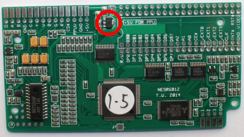
How to identify.
Genuine The genuine part has clear printing and a circular mould marking in the centre of its package, the text depends on manufacture date. |
Fake The fake part has poor quality printing, no mould marking, the text always reads HU1625 042. |
The part number is MCP1703T-3302E/MB manufactured by Microchip. The fake is probably a Chinese LM1117 or similar (eg. AMS1117-3.3).
The fake part is not a direct equivalent for the genuine one. The genuine part is designed for stability with a ceramic output capacitors in the 2-10 uF range. The fake part is probably meant to have an electrolytic or tantalum output capacitor in the 10-100 uF range. In some cases the fake voltage regulator will oscillate. Here's a video of this symptom.
Solution #1
Add an extra electrolytic capacitor between the 3.3V power rail and ground. This should make the fake regulator operate correctly and prevent oscillation. The easiest place to solder the capacitor is on the programming header. The positive leg of the cap should be soldered to pin 1 (encircled) which is 3.3V, the negative leg soldered to pin 2 which is ground. The capacitor should be either a 22 uF or 47 uF type - any voltage rating will do.")
Solution #2
The second, more difficult solution is to replace the fake voltage regulator with a genuine part. To remove it from the PCB you can use a hot air rework station or a soldering iron. The method for the soldering iron is to add extra solder to each of the three pins, then hold the iron in such a way as the tip is making contact with all three pins simultaneously. The thermal connection between the centre pin and the tab will eventually cause the solder to melt. Then the part will slide off the board.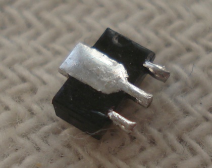
How to update the PLD software
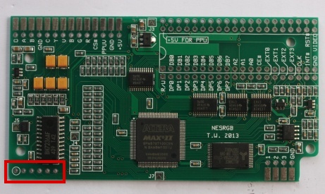
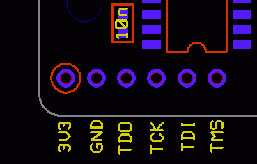
There is an umarked 6 pin JTAG programming connection on the lower left hand side of the board. Pin 1 is encircled.
JTAG Pinout
- VCC power rail
- Ground
- TDO
- TCK
- TDI
- TMS
The Altera USB Blaster requires the Quartus II Progammer Software for Windows to be installed. The download is 185 MB and installation requires 700 MB of hard disk space. The USB Blaster drivers are included in the package (find them in the folder after installation).
Downloads:
Quartus II Progammer Software
for Windows - Version 13.1 - working on Windows 7 and XP
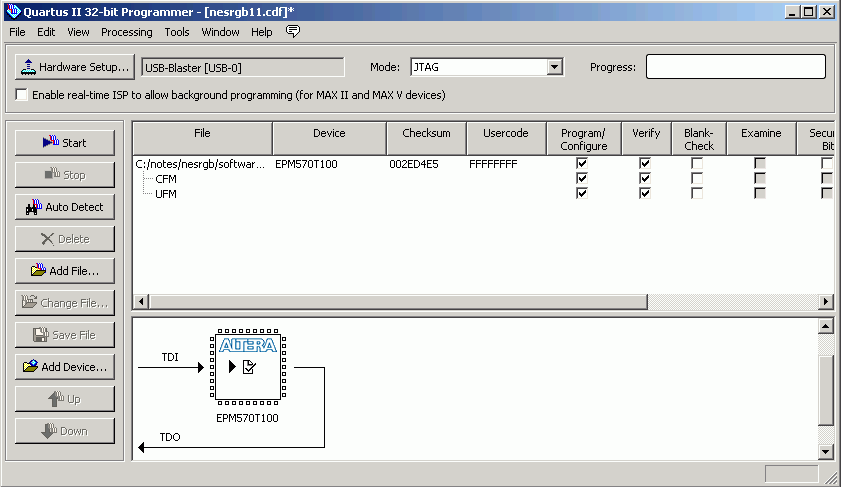
To use:
- Click Hardware Setup and select USB-Blaster from the list.
- File -> Open -> NESRGB11.POF
- Check the boxes for Program/Configure and Verify
- Make sure the programmer is connected to the NESRGB board
- Click Start