Guide for installing the N64RGB into all models of Nintendo 64
WARNING: THIS GUIDE IS OBSOLETE. PLEASE USE THE NEW GUIDE INSTEAD.
Tools and materials required:
- Soldering iron and leaded solder wire
- Screwdrivers - Philips and Nintendo head
- Sharp pair of side cutters
Click on the pictures to make them bigger.
 |
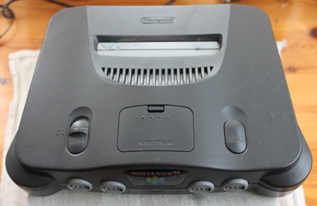
Open the Nintendo 64. Remove the power supply module (rear) and the jumper pack (top flap). Then remove the screws from the the bottom. You will need a special Nintendo shaped (gamebit) screwdriver for this. Never mind that 20 legged spider with the long black tail, I'll remove him now. |
 |
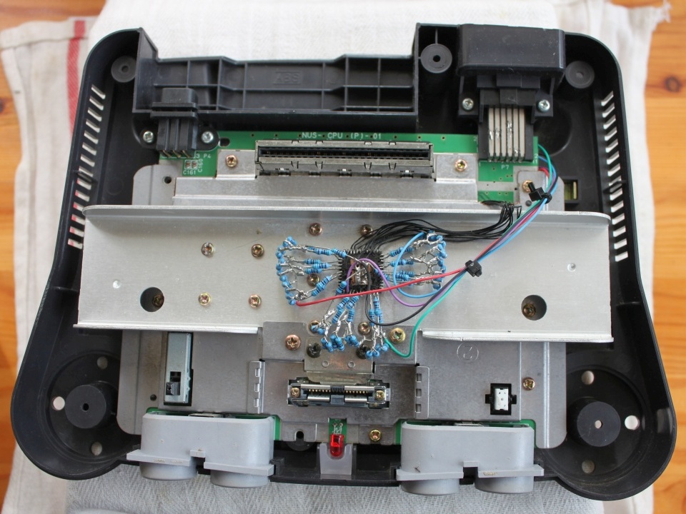
Take out the 14 screws holding the heat sink down. |
 |
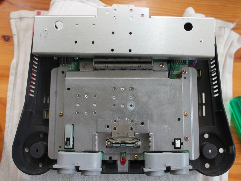
Remove the remaining screws around the motherboard and rear connectors. Also the two screws either side of the jumper pack slot. |
 |
 |
|
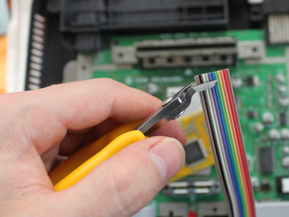
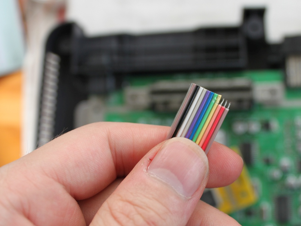
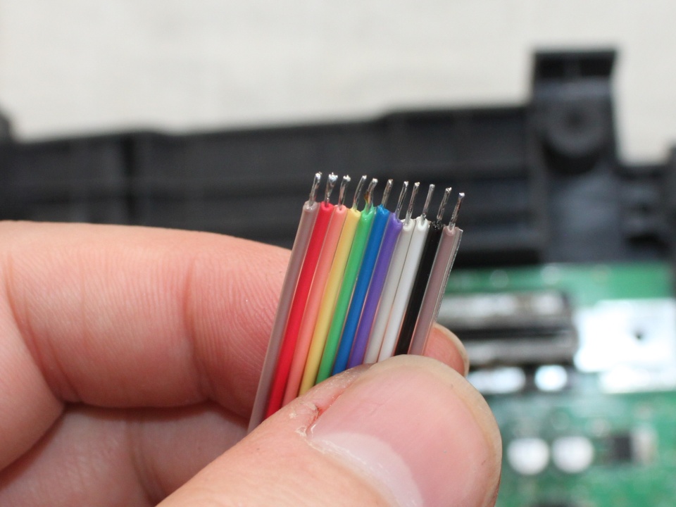
Find the wire included with the board. Strip the end with the
side cutters. It's easy to strip multiple wires at once. Then tin
the wires with solder. |
 |
|
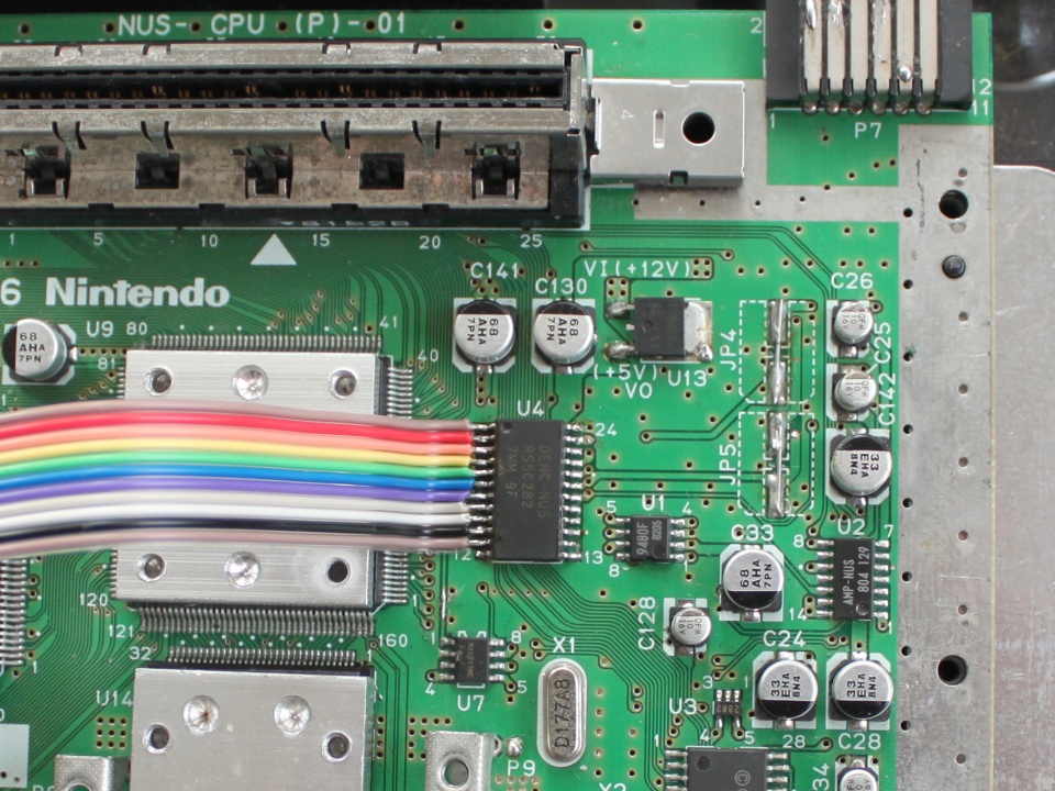 |
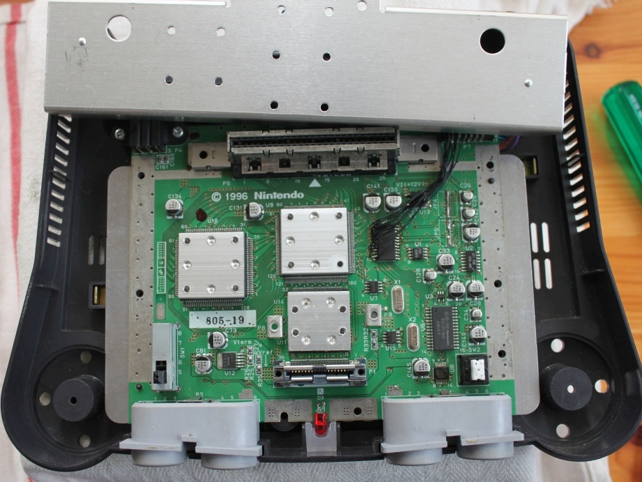
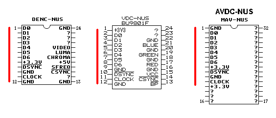
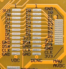
Locate the video DAC chip on the motherboard. You will find it
to the right of the largest IC on the board - the graphics
processor. There are 4 different DAC chips you may find. The DENC-NUS, MAV-NUS, VDC-NUS, and AVDC-NUS. Refer to the pin listings above. For the purposes of this guide, AVDC-NUS is the same as MAV-NUS. The N64RGB needs to be connected to the signals on the left side of the chip: D0-D6, DSYNC, CLOCK, +3V3, GND. Take note that these signal are on different pins for each DAC chip. In this case I have a DENC-NUS video DAC. Solder the wires to the appropriate pins on the DAC. Add some extra solder to each pin on that side of the chip. Hold the wire ribbon over the pins and apply pressure with the soldering iron to each wire in turn, soldering it to the pin. Take note which colours are on which pins. |
| |
 |
 |
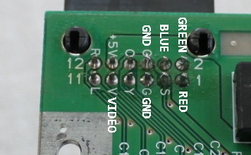
Turn the motherboard over and examine the A/V connector. Wires
for Red, Green, Blue, and Ground will need to be connected. I
recommend using two wires for ground for best performance. The connection of the (composite) Video wire is optional. You may choose to leave this signal alone and the composite video connection will work as usual. Alternatively, you may connect the sync signal (CS75) from the N64 board. Before connecting the new sync signal to this pin you must first cut the track of the existing signal. You can either do this close to the connector pin or follow the track back to a more suitable place. |
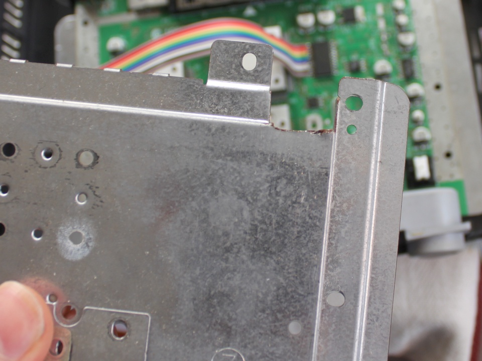 |
The metal radiation shield is in the way. I cut a piece out of it to let the wires through. Maybe is it only necessary to bend it slightly. |
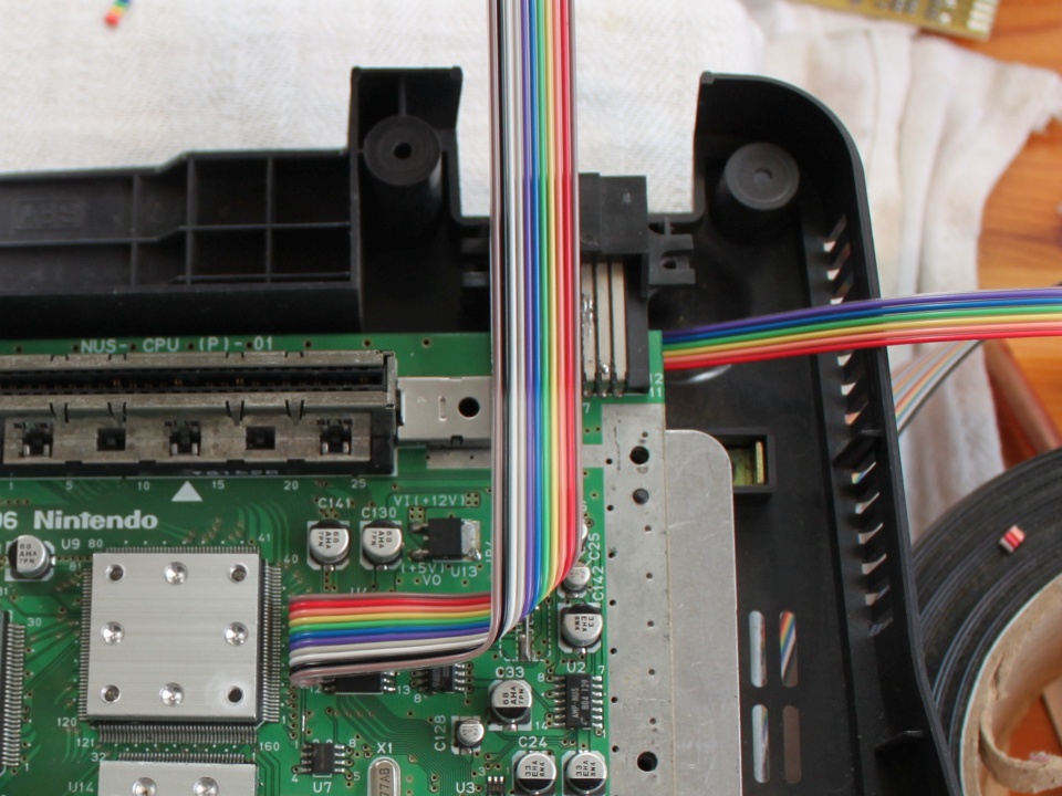 |
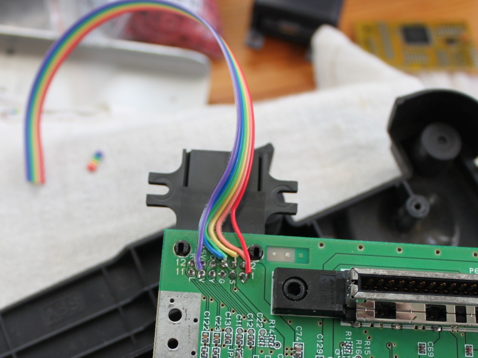
Arrange the wires like so. |
 |
 |
 |
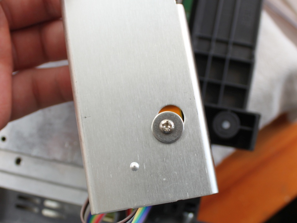
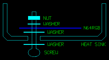
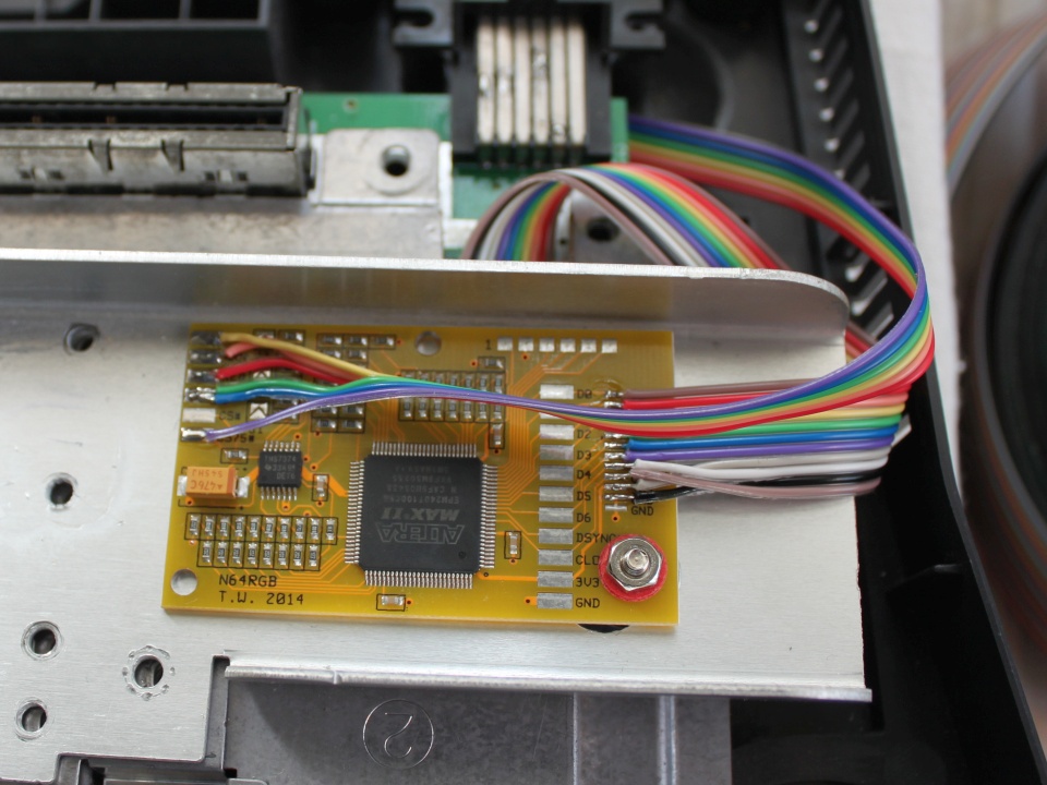
Mount the N64RGB board to the right hand side of the heat sink
using the mounting hardware provided. Version 1.0 When soldering the wires to the N64RGB you may choose the large pads or the small pads or a combination of the two, whatever you prefer. Here I will use the small pads. Add some solder to each pads on the N64RGB board before attempting to solder a wire to it. Refer to your notes on which wires carry which signals. The D0-D6 pads all line up with the order they are on the DAC chip, but the other four wires will certainly not. |
  |
Version 1.1 The board layout has three sets of pads for the three different DAC pin layouts. They line up exactly. Use liquid solder flux when soldering the fine pitch wire for MAV-NUS/AVDC-NUS. |
 |
Connect the RGB output wires. If you are connecting the sync
signal from the N64RGB board the CS75 signal should be used, not
CS# (which is a TTL level sync signal). This is the configuration for a Gamecube SCART cable. If you are intending to use a (PAL) Super Nintendo SCART cable you must add a blob of solder across jumpers J1, J2, J3 on the N64RGB board. |
| Plug in the power supply, jumper pack, SCART cable, and game and
test that the RGB video output is working correctly. The N64
should not be run for too long like this (without the heat sink
screwed down). If everything appears to work correctly you can put
all the screws back in. Perhaps leave out the screw who's access
hole the N64RGB board is now blocking. That's it - finished. |
|
Change Log
18/2/2015 - added some details about V1.1 hardware
11/10/2014 - Page created.