SCART Cable Set, assembly guide.
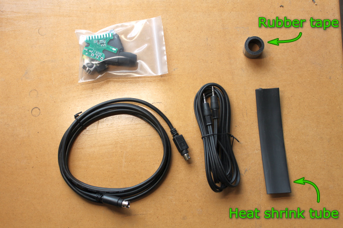 Contents of the cable set,
The older kits also contained a piece of heat shrink tube. In January 2020 this was replaced by a length self amalgamating rubber tape. |
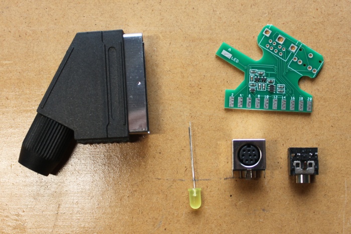 Inside the cable adapter kit is,
|
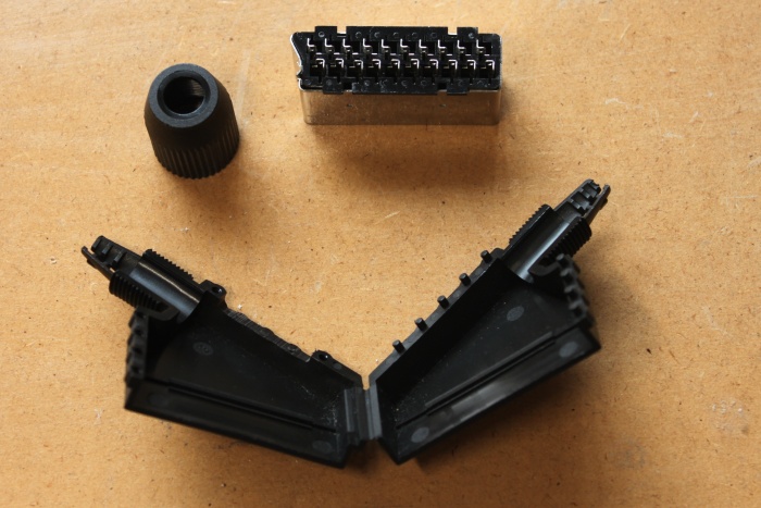 The first step is to assemble the cable adapter. Start by opening the SCART plug. To do this unscrew the end cap and pry the two halves apart. Notice that there is a slot cut in the top of the shell. This opening is cut for the circuit board to fit through. |
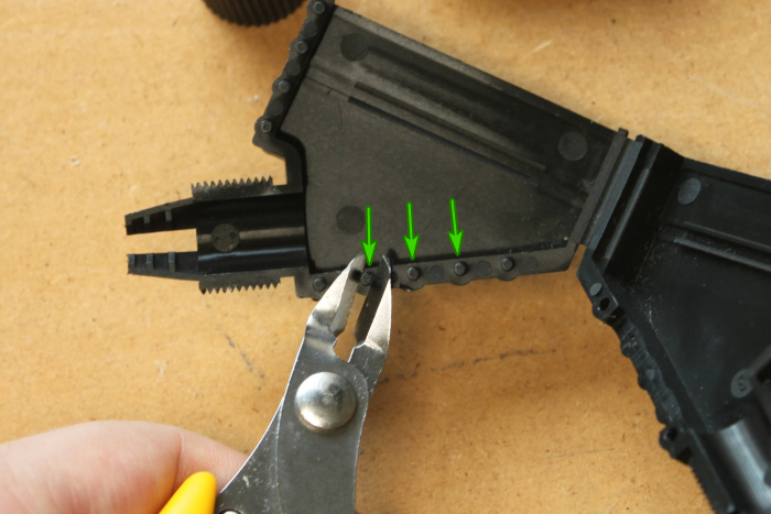 There are three plastic pegs located directly above the slot. Cut them off with a pair of side cutters. |
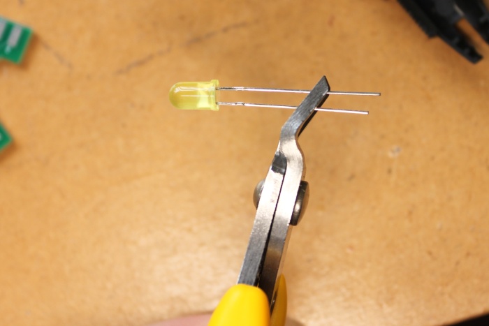 Using the same side cutters to shorten the legs of the LED. The longer leg is the anode, cut at an angle so the anode leg remains the longer one. |
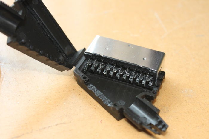 Place the pin block into the shell half which has the slot cut into it. It fits into the groove in the shell. |
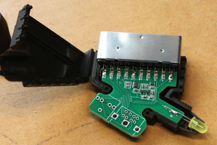 Insert the circuit board into the pin block and shell. Solder the two end pins 2 and 20. Place the LED into position as shown above. Make sure you get it the right way around. The anode pad is marked with 'A' on the board. 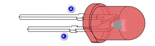 |
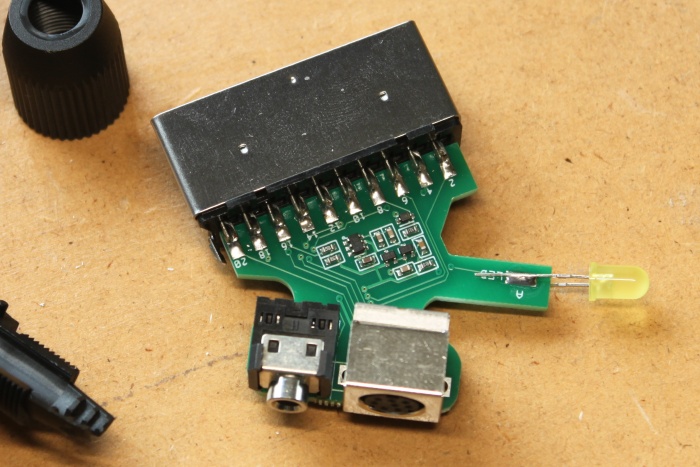 Remove the board from the shell and solder the rest of the SCART pins. Insert the 3.5mm and Mini Din sockets. |
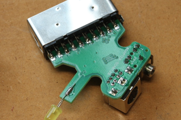 Flip the board over and solder all the pins of the SCART socket, the Mini Din socket, the 3.5mm socket, and the LED cathode pin marked with 'K'. |
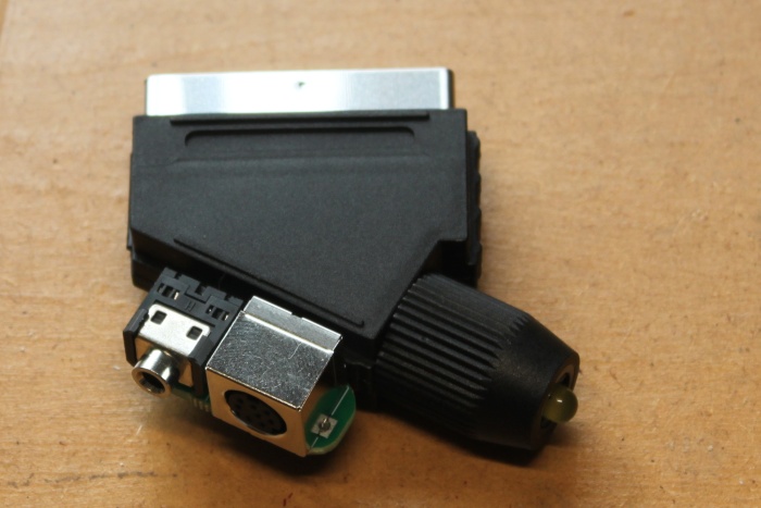 Put everything back into the shell, screw on end cap, done. |
The next step is to attach the audio and video cables together. Cable sets sold before January 2020 comes with a length of 20mm heat shrink tube. This type of heat shrink contains hot glue on the inside and will shrink to a quarter of its original size. The problem was that it required a lot of heat to shrink. A heat gun was required (a hair dryer doesn't get hot enough). The current cable set currently contains a length of self amalgamating rubber tape. It doesn't require any special tools to apply. If you have cable set that came with rubber tape then click here, otherwise keep reading. |
 Cut the length of heat shrink tube into six rings of equal size. |
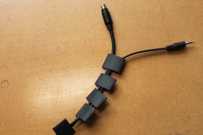 Thread the audio and video cables through each ring. |
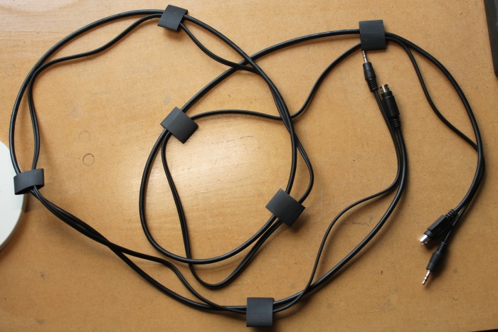 Space the rings along the cable pair, about 250mm between each. |
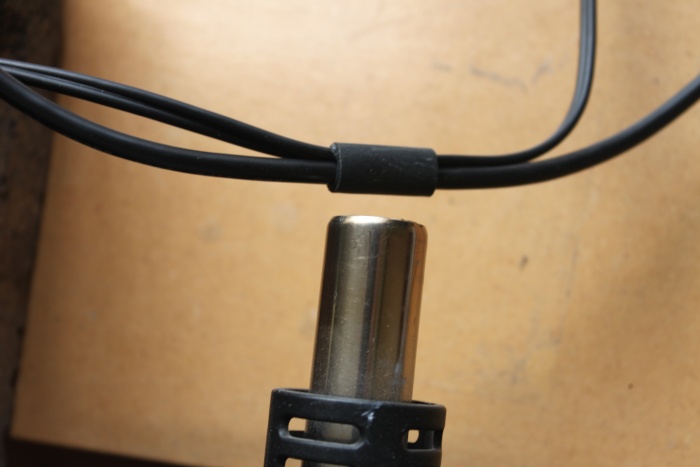 Use a heat gun or hot air rework station shrink each ring. A hair dryer will not work for this job. |
 Complete. |
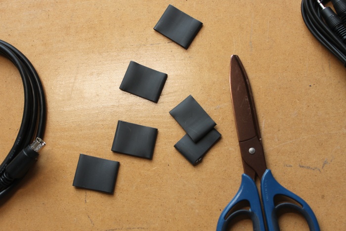
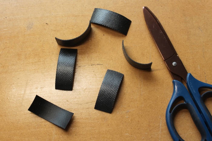 Cut the length of rubber tape into 6 pieces of equal size (about 50mm each). |
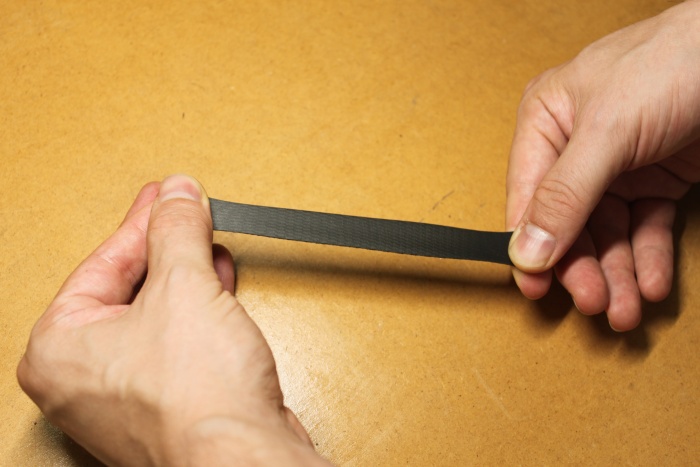 Take one piece of tape, peel off the transparent backing material, and stretch it three or four times its original length. |
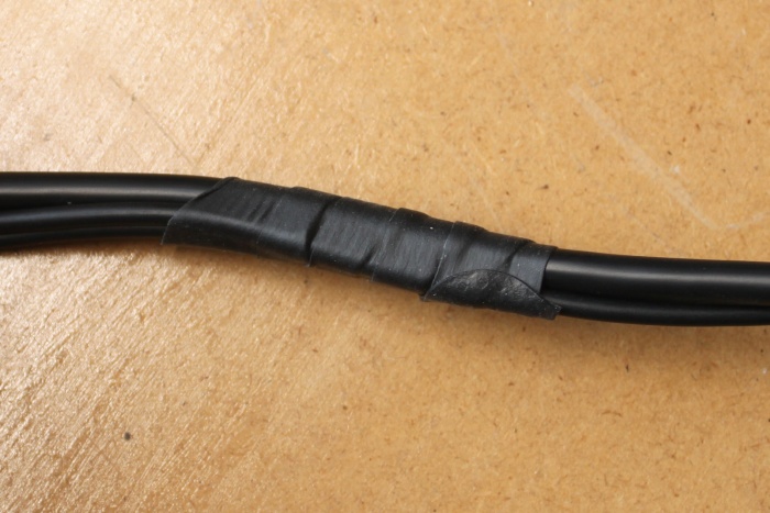 Wrap the rubber tape around the cable pair while keeping the tape stretched. Each time it should overlap itself by 50% |
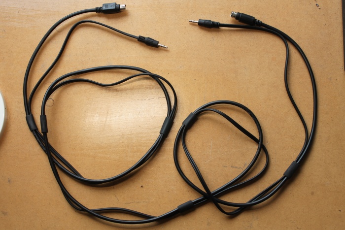
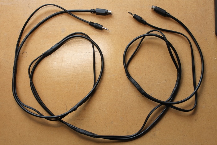 Repeat the process for each piece of rubber tape. Space them evenly along its length, about every 250mm. |
Change log.
17/1/2020 - Completely rewrote instructions to keep up to date with the current cable set. The boost converter is now merged with the main circuit board and the SCART plug is now supplied with the slot already cut into it. Also added information about how to attach the audio and video cables together.
2014 - Page created.