AV-Driver Jumper Settings and Technical Info
The AV-Driver board features:- Audio Driver * 2 channels
- Video Driver * 4 channels
- Sync Driver * 1 channel
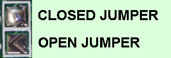
The parameters for each circuit are set via solder jumpers on the top side of the board. All jumpers are open by default. To close a jumper, just add solder. In the tables below, an open jumper is represented by a '0' and closed by a '1'. Solder on the jumper side of the AV-Driver board only.
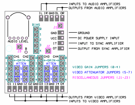
Video Gain
The gain of the video amplifier is variable between 1 and 4.1 in 0.1 steps.The gain must be the same for each channel.
The bias value is the same as the gain value.
j = (a - 1) * 10
Where 'j' is the binary value of the gain jumpers and 'a' is the desired voltage gain.
Alternatively, refer to the table below.
|
|
|
|
Video Attenuator
There is an attenuator before the amplifier. This is useful when the
input signal amplitude is too large.
There are only three valid settings for the attenuator.
The attenuator should be set the same
for each channel.
| Attenuation |
765 (jumpers) |
| no attenuation | 001 |
| divide by 3 | 010 |
| divide by 6 | 100 |
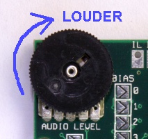
Audio Level
This is set with the audio level potentiometer.
Other Jumpers J1, J2, J3
| Level for Sync Input (IT) |
J1 |
| Low level (for PC Engine/Turbografx) | 0 |
| TTL level | 1 |
| Level for Sync Output
(OT) |
J2 |
| TTL level | 0 |
| 75 ohm (recommended) | 1 |
All TV sets and most monitors work best with 75 ohm sync. Some exotic
monitors require TTL sync.
| Power On Audio Pop
Suppression |
J3 |
| Enabled (recommended) | 0 |
| Disabled | 1 |
Pop suppression must be disabled when the power supply voltage is less than 4.5V.
Other Details
The board size including volume control is 41.5 * 30.5 * 6.5 mm.
Operating voltage range is 3-5 V.
Typical quiescent current is 20 mA with J2 open and 30 mA with J2 closed.
Operation Diagram
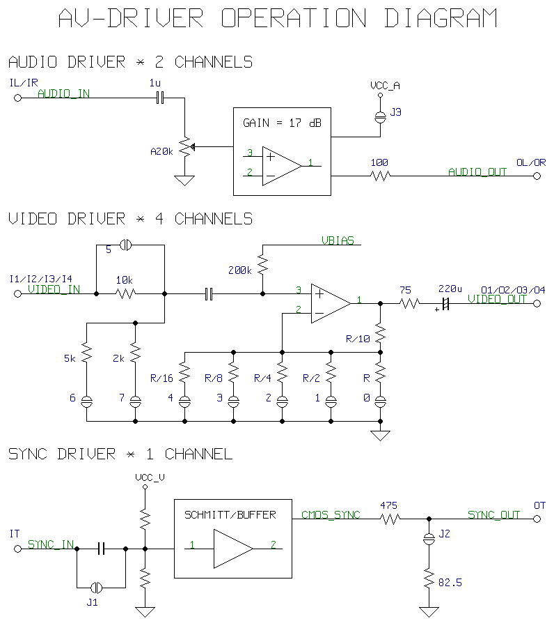
Download the complete circuit diagram (PDF)
Change Log
9/6/2016 - Page created.