Pin Listings for JAMMA-Prog


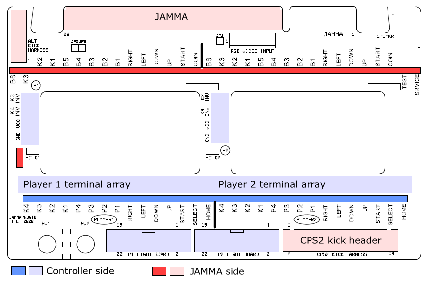
The words in bold match the white silkscreen writing on the PCB. This way you can easily see where each pin on the pin strip goes.

JAMMA Side

JAMMA (card edge, 56 finger, 3.96mm)
Top/component side Bottom/solder side
  • 1. Ground
  • 2. Ground
  • 3. +5V
  • 4. +5V
  • 5.
  • 6. +12V
  • Key cut out
  • 8.
  • 9.
  • 10. Speaker+ (Neo Geo right)
  • 11.
  • 12. Red out
  • 13. Blue out
  • 14. RGB ground (ground if JP1 closed)
  • 15. TEST switch
  • 16. Jamma P1 COIN
  • 17. Jamma P1 START
  • 18. Jamma P1 UP
  • 19. Jamma P1 DOWN
  • 20. Jamma P1 LEFT
  • 21. Jamma P1 RIGHT
  • 22. Jamma P1 button 1 B1
  • 23. Jamma P1 button 2 B2
  • 24. Jamma P1 button 3 B3
  • 25. Jamma P1 button 4 B4
  • 26. Jamma P1 button 5 B5
  • 27. Jamma P1 button 6 B6 (ground if JP2 closed)
  • 28. Ground
  • A. Ground
  • B. Ground
  • C. +5V
  • D. +5V
  • E.
  • F. +12V
  • Key cut out
  • J.
  • K.
  • L. Speaker- (Neo Geo left)
  • M.
  • N. Green out
  • P. Sync out
  • R. SERVICE switch
  • S.
  • T. Jamma P2 COIN
  • U. Jamma P2 START
  • V. Jamma P2 UP
  • W. Jamma P2 DOWN
  • X. Jamma P2 LEFT
  • Y. Jamma P2 RIGHT
  • Z. Jamma P2 button 1 B1
  • a2. Jamma P2 button 2 B2
  • b2. Jamma P2 button 3 B3
  • c2. Jamma P2 button 4 B4
  • d2. Jamma P2 button 5 B5
  • e2. Jamma P2 button 6 B6 (ground if JP3 closed)
  • f2. Ground

Alt Kick Harness: (KF2510, 8 pin, 2.54mm)
  1. Jamma P1 kick 1 K1
  2. Jamma P1 kick 2 K2
  3. Jamma P1 kick 3 K3
  4. Ground
  5. Jamma P2 kick 1 K1
  6. Jamma P2 kick 2 K2
  7. Jamma P2 kick 3 K3
  8. Ground
CPS2 Kick Harness: (Hirose, DF1B-34DP-2.5DSA, 34 pin, 2.5mm)
  • 2.
  • 4.
  • 6.
  • 8.
  • 10.
  • 12.
  • 14.
  • 16.
  • 18.
  • 20.
  • 22.
  • 24.
  • 26.
  • 28.
  • 30.
  • 32.
  • 34. Ground
  • 1.
  • 3.
  • 5.
  • 7.
  • 9. Jamma P2 kick 3 K3
  • 11.
  • 13.
  • 15. Jamma P1 kick 3 K3
  • 17. Jamma P1 kick 2 K2
  • 19. Jamma P1 kick 1 K1
  • 21. Jamma P2 kick 1 K1
  • 23. Jamma P2 kick 2 K2
  • 25.
  • 27
  • 29.
  • 31. Ground
  • 33. Ground

RGB Video Input: (KF2510, 7 pin, 2.54mm)
  1. Ground
  2. 5V power output
  3. RGB ground (ground if JP1 closed)
  4. Blue input
  5. Green input
  6. Red input
  7. Composite sync input

Speaker: (JST, B5P-VH-FB-B, 5 pin, 3.96mm)

  1. +5V output
  2. +12V output
  3. Ground
  4. Speaker+ (Neo Geo right)
  5. Speaker- (Neo Geo left)

Controller Side

P1 Fight Board: (IDC box header, 20 pin, 2.54mm)
  • 1. P1 controller, UP
  • 3. P1 controller, RIGHT
  • 5. P1 controller, SELECT
  • 7. P1 controller, START
  • 9. P1 controller, 2P
  • 11. P1 controller, 4P
  • 13. P1 controller, 1K
  • 15. P1 controller, 3K
  • 17. Ground
  • 19. P1 controller, power VCC 
  • 2. P1 controller, DOWN
  • 4. P1 controller, LEFT
  • 6. P1 controller, HOME
  • 8. P1 controller, 1P
  • 10. P1 controller, 3P
  • 12. Ground
  • 14. P1 controller, 2K
  • 16. P1 controller, 4K
  • 18. Ground
  • 20. P1 controller, power VCC

P2 Fight Board: (IDC box header, 20 pin, 2.54mm)
  • 1. P2 controller, UP
  • 3. P2 controller, RIGHT
  • 5. P2 controller, SELECT
  • 7. P2 controller, START
  • 9. P2 controller, 2P
  • 11. P2 controller, 4P
  • 13. P2 controller, 1K
  • 15. P2 controller, 3K
  • 17. Ground
  • 19. P2 controller, power VCC 
  • 2. P2 controller, DOWN
  • 4. P2 controller, LEFT
  • 6. P2 controller, HOME
  • 8. P2 controller, 1P
  • 10. P2 controller, 3P
  • 12. Ground
  • 14. P2 controller, 2K
  • 16. P2 controller, 4K
  • 18. Ground
  • 20. P2 controller, power VCC

Terminal Array: (KF127, 2/3 pin, 5.08mm) Pins listed in anticlockwise order.


Change Log
16/6/2020 - Page created.