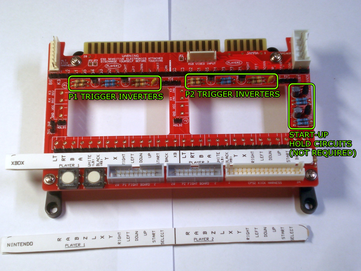
The trigger inverter circuits will need to be fitted because the Xbox 360 game pad features analog triggers.
The start-up hold circuits, as well as the 20 pin fighting board headers will not be used and can be omitted.
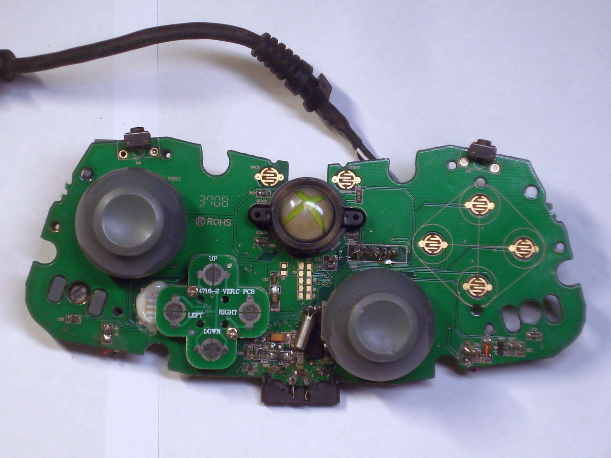
Determine that the PCB uses a common ground layout. That is, one side of each button is connected to ground. This can be verified by with a multimeter on continuity mode.
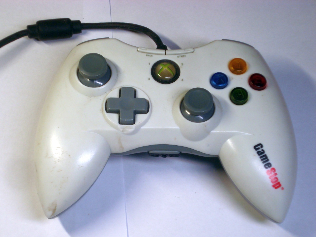
Matrix button layouts, which some genuine Microsoft Xbox 360 controllers have, are unsuitable for game pad hacks of this nature.
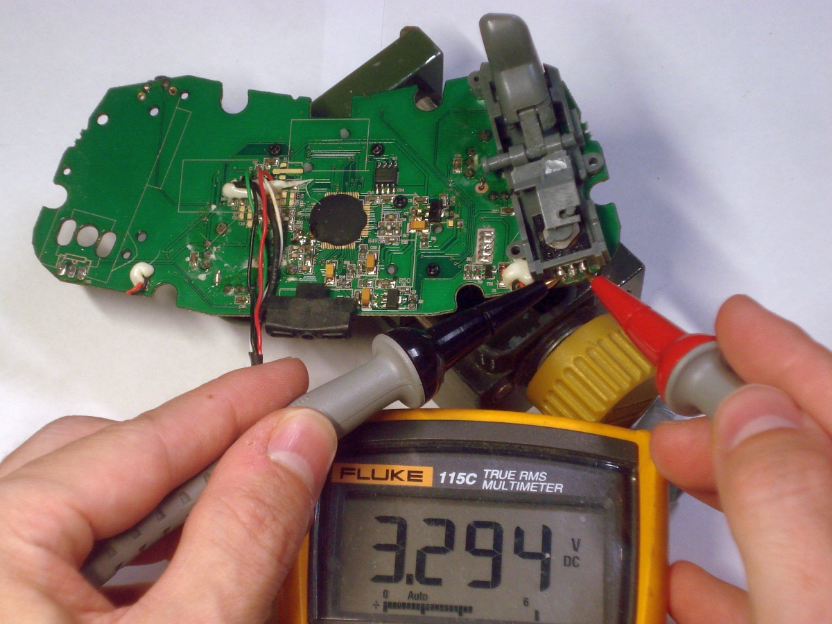
One side of the trigger potentiometer is ground, the other is VCC, with the wiper in the middle. Plug the controller into a USB port and use a multimeter set on the DC volts range to determine which is which.
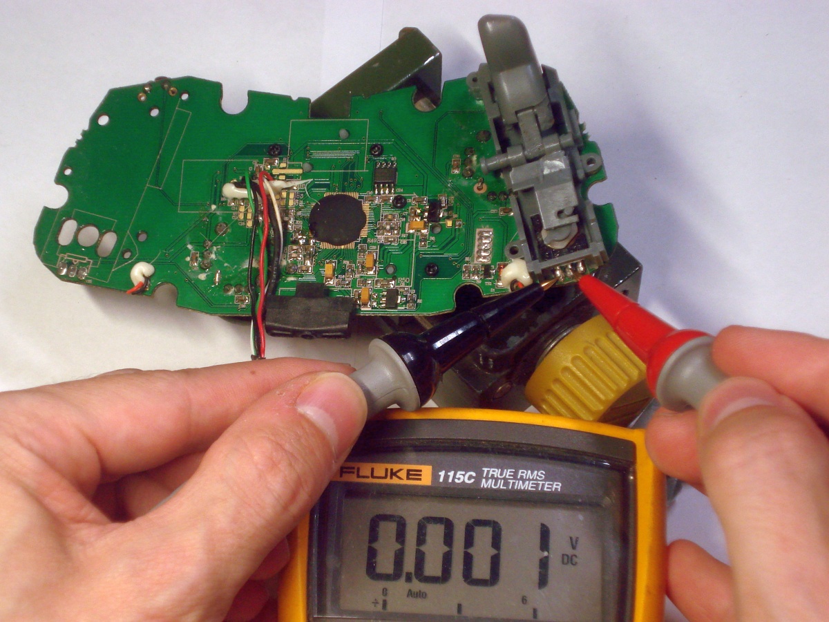

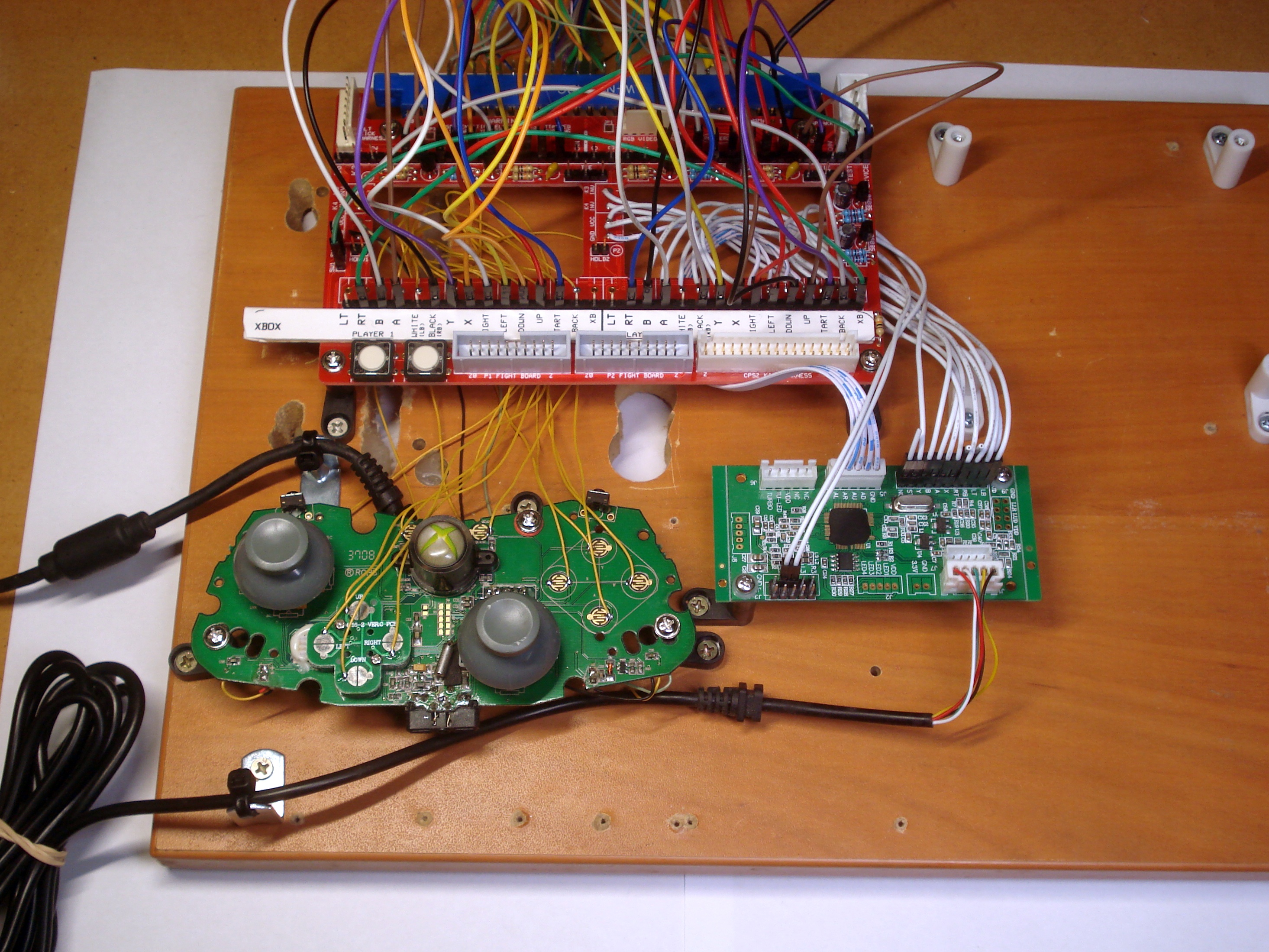
Remove both left and right trigger potentiometers. Solder a wire to one of the potentiometer's VCC pads. Solder another wire to the potentiometer's ground pad. These will be connected to player 1 VCC and GND respectively on the JAMMA-Prog.
This VCC is 3.3V and it powers the trigger inverter circuits. Do not use the 5V USB bus power for VCC.
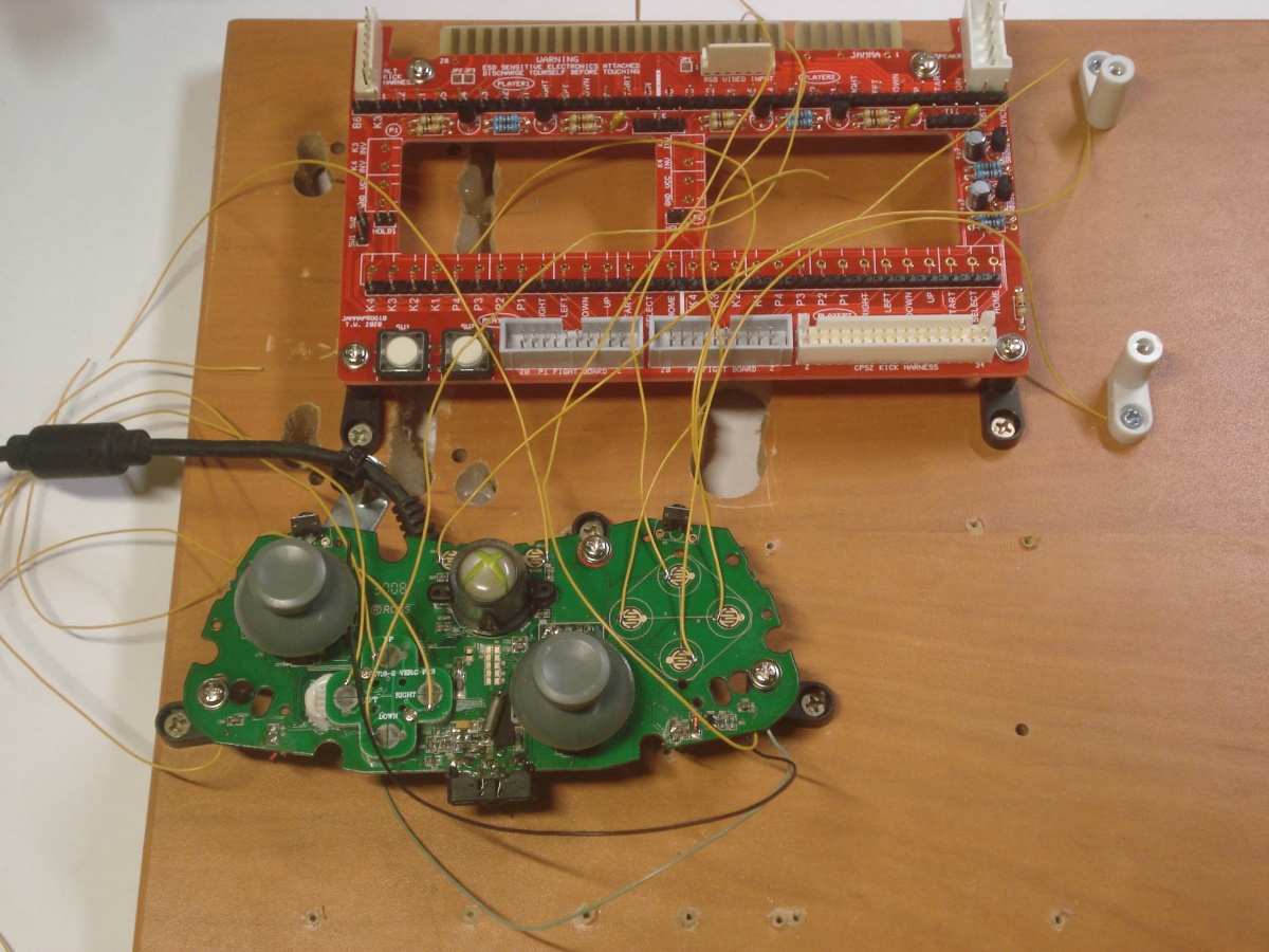
The wiper from the left trigger is connected to K4 INV JAMMA-Prog and the wiper from the right trigger is connected to K3 INV on the JAMMA-Prog.
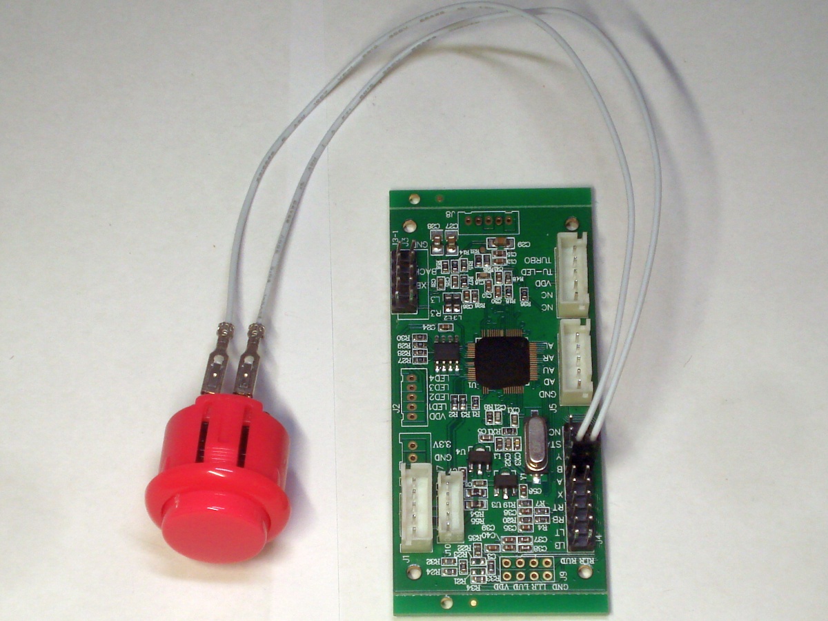
Note that I have soldered the wire to the wrong side of the X button (the ground side) by mistake in the photo.

The reason for this is the chipset unused inside the arcade stick is the same one that's found inside a regular game pad. It's just using the analog input in a digital fashion. To connect this input to a standard JAMMA common ground switch, a trigger inverter circuit will be required, just like a the game pad hack.
Just to make it clear, the 3.3V from the switch header is used for VCC, not the 5V USB bus power.
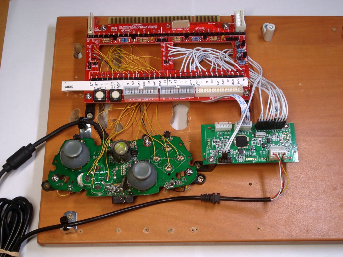
Attach the USB cable to a bracket of some kind with a cable tie. This functions as a strain relief, which is necessary to prevent the USB cable from being ripped out from its controller board.